

We will take a look at an Infiniti suffering from a timing problem.
It has been said that time waits for no one, and that is certainly true for auto technicians. There is always a vehicle to diagnose or a repair that has to be done by the end of the day. There are classes to attend, articles to peruse, webinars to watch and certification tests to take. All of these things take time and often leave a technician scrambling to keep up.
It has also been said that timing is everything, and for the internal combustion engine there may not be a more true statement. Milliseconds separate correct combustion from a misfire and proper valve timing from a damaged engine. In this edition of Nissan TechNews, we will take a look at an Infiniti suffering from a timing problem.
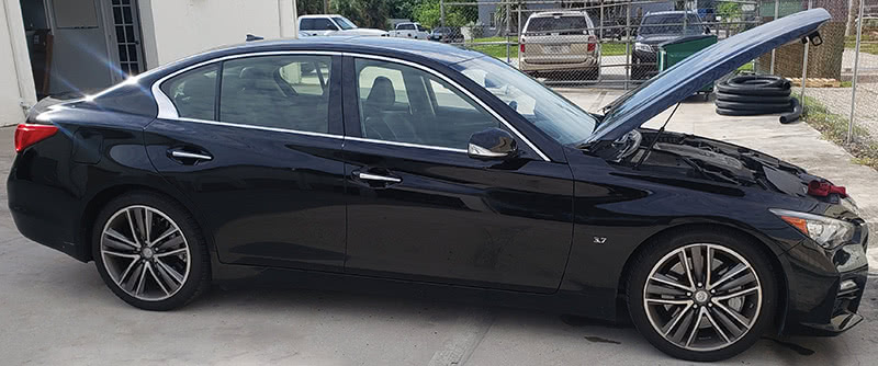
The vehicle in question is a 2015 Infiniti Q50 with a 3.7L engine. During the initial client interview, the owner stated that the Check Engine light was on and the engine was running rough and low on power. The current mileage was 64K and the vehicle had only been seen once before at 61K miles, so there was limited service history.
Checking the records from the previous visit showed a similar issue to the current complaint. At that time the Check Engine light was also on with the engine running poorly. A P0301 cylinder 1 misfire fault code was retrieved from the engine control module. The notes stated that the ignition coil and fuel injector circuitry all tested OK before the ignition coil was removed in order to check spark output.
The spark output of the coil was acceptable, so the spark plug was removed for inspection. Surprisingly, the spark plug already showed noticeable signs of engine oil deposits, and was the likely cause of the misfire. The notes went on to show that the spark plug was cleaned off in order to verify the misfire would be resolved, and that the owner was advised the engine was consuming oil. An induction service, spark plug replacement, and further checks on the cause of the oil consumption were recommended at that time; however the client elected to reschedule for a future visit.
Before getting any deeper into our Infiniti’s current issue, let’s take a few moments and talk tech on this vehicle. Powered by a 3.7L engine coupled to a 7 speed automatic transmission, the Q50 replaced the G40 and Q40 for the 2014 model year. The vehicle uses Nissan’s FM platform, which is a front mid-ship design that moves the engine as far back to the firewall as possible, thus redistributing some of the powertrain weight off the front suspension to the middle of the vehicle. This design also allows the front wheels to be moved further towards the corners of the vehicle for better handling. There is a 3.5L hybrid version of the sedan available as well as an all-wheel drive option.
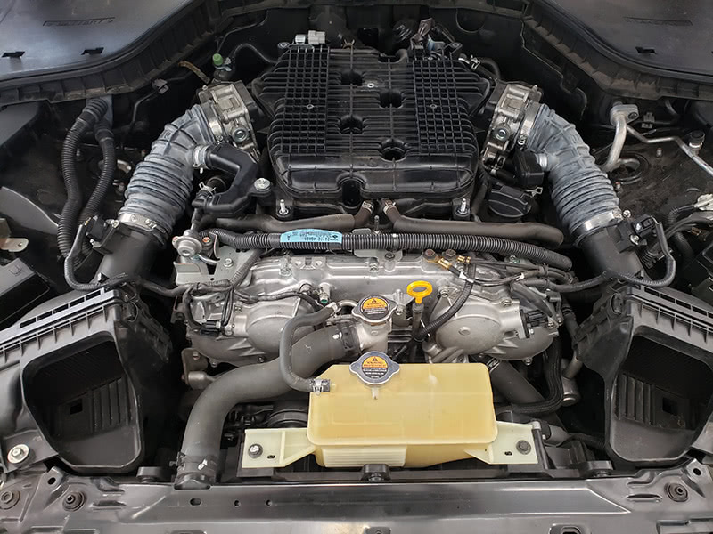
The Q50 is powered by a VQ37VHR six cylinder engine. The engine is mounted longitudinally with the right cylinder head being Bank 1 and containing the odd numbered cylinders. The firing order is consecutive from cylinder 1 through cylinder 6.
Now let’s take a look at the last three letters in the engine code: VHR.
- The ‘V’ means the engine uses variable valve lift. In fact, this engine employs Variable Valve Event and Lift (VVEL) technology, which precisely controls not only valve event timing, but the event duration as well. The valve lift control is accomplished through an eccentric cam and stepper motor that act on two links on the output camshaft, while variable cam timing operates with adjustable intake camshaft gears.
- The ‘HR’ denotes High Response and High Revolution. According to Nissan, these engines are designed to have a higher rate of revolution, redlining at 7,500 rpm, and outstanding accelerator response. That accelerator response is courtesy of dual throttle bodies and Mass Air Flow (MAF) sensors. These twin intake components are seamlessly blended together by the engine control module software.
All of this variable valve timing technology uses engine oil to lubricate and cool the components and provide the hydraulic pressure needed for the system to work. Speaking of oil, Infiniti recommends the use of Nissan Ester Oil for this engine, but at an MSRP of over $12 per quart, the initial factory fill is often the only time one of these engines is running on the specified oil. Lesser quality oils and extended service intervals will result in premature engine wear and a shorter than expected lifespan. The factory service interval for engine oil is 5K miles on this Q50, but as we will see it is critically important that the oil level is checked in between services.
All right, time to get back to our ailing Infiniti. A full system code scan was performed, which revealed not the expected misfire code to have come back, but a P0011. According to service information, a P0011 fault is for the intake camshaft position for Bank 1.
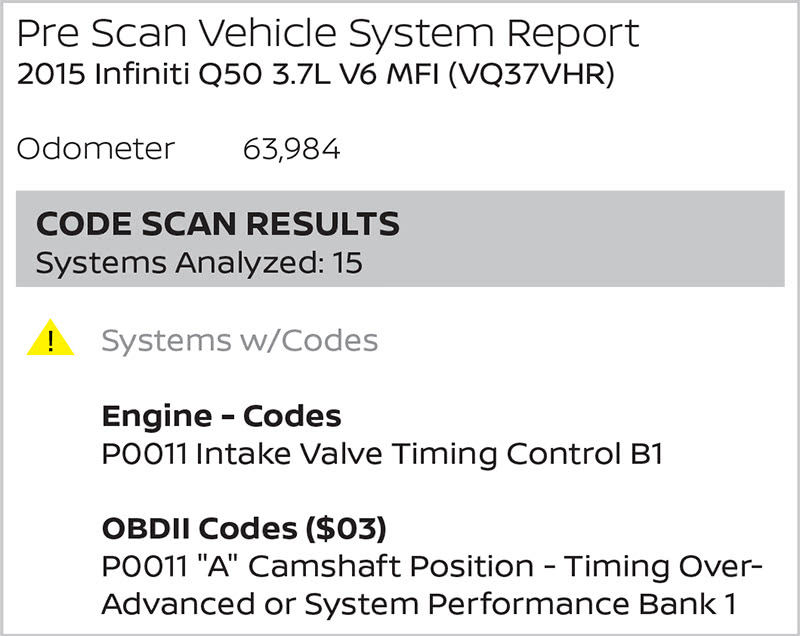
The code sets when there is a gap between the angle of the target and the phase-control angle degree; target in this case meaning the trigger wheel on the front of the cam gear. When the code is set, the intake valve timing control solenoid is no longer energized so the valve control does not function.
| DTC No. | CONSULT screen terms (Trouble diagnosis content) | DTC detecting condition |
|---|---|---|
| P0011 | INT/V TIM CONT-B1 (“A” camshaft position – timing over-advanced or system performance bank 1) | Ther is gap between angle of target and phase-control angle degree. |
| P0021 | INT/V TIM_CONT-B2 (“A” camshaft position – timing over-advanced or system performance bank 2) | Ther is gap between angle of target and phase-control angle degree. |
The engine was started and a road test was next. Upon acceleration out of the service lot, an extremely troubling engine noise was heard. The road test was abruptly halted, and the vehicle was gingerly driven back to the service bay. The logical first question was, how much oil is or isn’t in the crankcase? The dipstick was removed, wiped clean, reinserted then removed to check the level.
Suspicions confirmed; there was nothing registering on the dipstick at all.
Given the fact that variable valve timing works off oil pressure, and that there was barely any oil in the system, bringing the oil level back to specifications was the obvious first step. Adding four quarts of oil brought the level back into operating range. Four quarts! The specification for the crankcase was just over five quarts, so this engine was running on less than two quarts of oil.
Referring back to the records from the previous service showed the oil level was only marginally low at that time. This engine had apparently lost almost four quarts of oil in just over 2,300 miles. A quart of oil every 500 miles surely seems excessive. The next logical question was, where did all the oil go? Inspection revealed that there were no exterior oil leaks worth mentioning, therefore the engine must have consumed the oil.
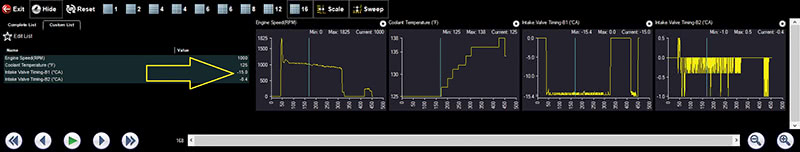
At this point however, there was still a diagnosis to be performed on the P0011 DTC. Now that the oil level was correct and the horrible engine noise was gone, a road test was performed while capturing relevant data PIDs. After reviewing and saving the DTC and freeze frame data the code was cleared KOEO. It was discovered that within a very short period of time after startup the code would reset and all camshaft control would cease. However, the camshafts were controlled for a moment by being advanced, and then returned to a rest position of zero degree offset. At this point the Bank 1 camshaft would actually drop to -15 degrees, while the Bank 2 camshaft stayed right around 0 degrees.
The testing so far had shown the Variable Valve Timing components were operational, yet the Bank 1 camshaft was reading beyond acceptable limits. Clearing fault codes while the engine is running is not typically recommended, but in this case any further testing with the scan tool was going to be fruitless.
The attempt was made to clear codes while driving in the hopes that the cams would stay in an advanced position in order to gather further data. This did actually work, and after clearing codes the camshafts appeared to be in sync with each other through most operating conditions. When the engine was brought back down to idle, the Bank 1 camshaft would again drop well below its target, the limited power could be noticed, and the Check Engine lamp illuminated indicating the fault had returned. This process was repeated several times and then a return to the shop was in order.
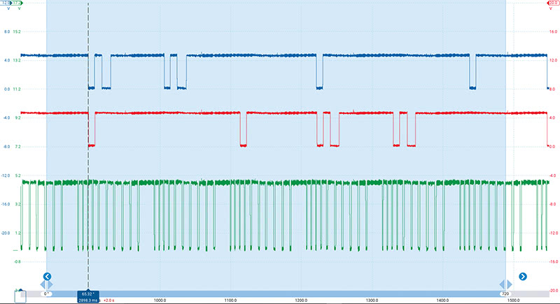
All visual and scan tool testing had been completed, so it was time to bring out a lab scope to verify what the engine computer was seeing from the engine position sensors. A total of three lab scope channels were needed to connect to each camshaft and crankshaft signal wire. The engine was cranked over and the following waveform was captured. Channel A in blue is the Bank 1 camshaft position sensor, Channel B in red is the Bank 2 cam sensor and Channel C in green is the crankshaft position sensor signal.
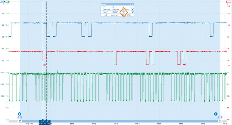
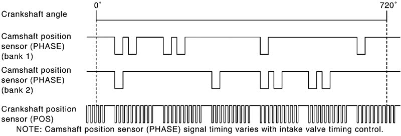
Thankfully, Nissan provided a signal reference diagram in the service information. According to the diagram, the leading edges of the Bank 1 and Bank 2 camshaft signals should line up with each other vertically, although they are offset by one cycle. Where the Bank 1 signal starts with two double pulses followed by two single pulses, Bank 2 displays the opposite pattern.
Using Picoscope’s zoom and ruler functions and comparing to the known good example, it was clear that the Bank 1 camshaft was off by about 13 degrees. This confirmed what the scan tool data was showing and why the fault code was setting. Using the cam and crank signals for comparison in this way is a powerful method of ‘seeing’ inside an engine before tearing it down. When disassembling an engine it is best to know ahead of time what to be looking for; exploratory tear downs can lead to guessing and unnecessary repairs.
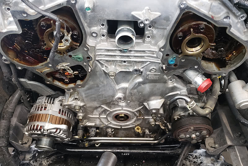
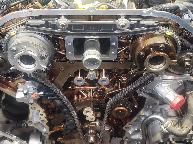
With all testing indicating that the Bank 1 intake camshaft was indeed out of time, the call was made to remove the front covers and check the timing chain alignment marks. The cooling fans and front accessories needed to be removed first followed by the timing control covers. The lower section of the oil pan also needed to be removed to access the two upper oil pan bolts that thread into the timing cover. All the remaining bolts that hold the timing cover in place were removed next and the cover was carefully pried free from the engine block. Great care must to be taken when removing the timing cover to not damage the sealing surfaces.
With the harmonic balancer bolt temporarily rethreaded into the crank, the engine was turned over multiple times to line up the timing marks and the painted timing chain links. Surprisingly, the marks and links all lined up! What seemed like a cut and dry jumped timing chain was no longer the case.
Reviewing the code trouble shooting information brought up a list of other possible causes for the P0011 trouble code. They included a faulty crankshaft or camshaft sensor, an intake control solenoid valve, a buildup of debris to the signal target wheel of the camshaft, or a clogged oil groove for the intake valve timing control solenoid.
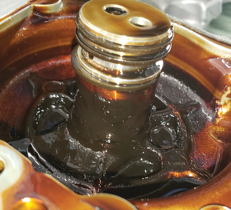
The engine position sensors had already been verified with the lab scope testing. Each of the control solenoid valves were bench tested and found to be working correctly. There was some sludge build up under the timing cover. While it did not appear to be excessive enough for the oil passages to be restricted, the components and passageways were cleaned. That left the signal target wheel as the most likely cause of the cam position fault.
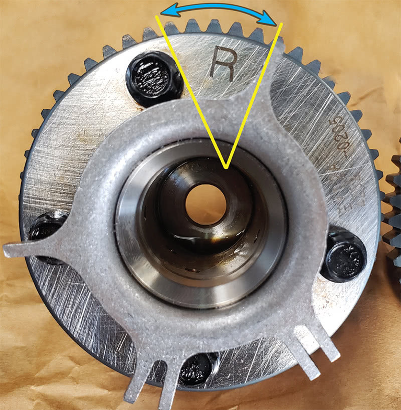
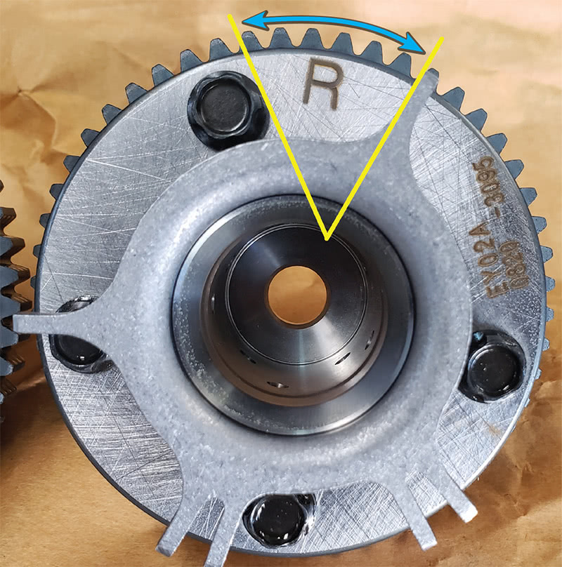
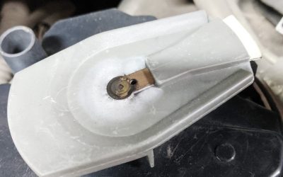
Further research revealed that the target or trigger wheels on this Q50 are press fitted onto the front of the intake cam sprockets. The camshafts only advance from a zero position with variable valve timing, so the cam position data PIDs should not read a negative value. Since the timing chain had not jumped, the target wheel must have shifted position. The call was made to the owner of the vehicle and the part was ordered from the Infiniti dealer.
Once the new camshaft gear arrived the parts were compared, and while the difference was slight, the target wheel was definitely shifted on the old gear. With the sprockets side by side, it was clear that the target wheel had moved counterclockwise about one tooth. This could be further proven by counting the teeth of the cam sprocket and using some basic mathematics.
The cam sprocket has 52 teeth. Dividing the 360 degrees of a circle by 52 teeth equals 6.923 degrees of rotation per tooth of the cam sprocket. Now double that number to 13.846 degrees to get the crankshaft rotation degrees due to the camshaft turning at half the speed of the crank. The resulting number is very close to the lab scope and scan tool readings of the Bank 1 intake camshaft being 13 – 15° retarded in relation to the crankshaft.
The VQ37 engine was reassembled with new chains, guides, tensioners, and the new intake cam gear. After carefully cleaning the old liquid gasket from the mating surfaces of the engine block and timing cover, a 3.5 mm bead of silicone RTV gasket maker was applied. The timing cover was reinstalled and properly torqued. Then the oil was changed, adaptations reset, and the code cleared.
After an initial road test was successful, an extended drive was performed. No fault codes or warning lights were noted on the drive and the Q50 was running beautifully. Back at the shop a follow up cam crank waveform was captured and analyzed. Now the camshaft signals lined up with each other just as service information indicated they should.
While camshaft to crankshaft correlation waveforms hold valuable data, it is important to remember their limitations. The waveform is only showing the position of the trigger wheels in relation to each other. This leaves a variety of other possibilities to keep in mind: air gap of the sensor, shifted or damaged trigger wheel or keyway, incorrect new or used parts installed.
Now that our Infiniti has its timing straightened out, the oil consumption issue needs to be dealt with to prevent any more engine problems. That will have to wait for another day, though; it is time for us to go!
By Jordan Hill and Preston Pollen


Same as of my Nissan Sentra Series 3, B14. Its head gasket was changed due to oil-coolant mix, unfortunately the mechanic did not timed it correctly. Now, although it crank, it refuse to start. I verify the failed timing, when I open the camshaft cover, turn the crankshaft through its pulley bolt, put it in Top dead center, while the distributor rotor, point No. 1 of the distributor pin, and found that the timing chain, even in how many rotation does not point to the sprocket mark. It is two teeth away. Deem I need to disassemble it again to put to proper timing. Sad.
Installed a new actuator on a 370Z once and unbeknownst to me the box had been dropped.
One reluctor arm was bent. Hard to see without comparing. Take a good look at the box on all your new parts.