Â
We all want clean air. We thrive in it. We breathe it in, turn it into power and exhale it. Our vehicles do exactly the same thing. The process of internal combustion is not 100 percent efficient, however. Not all the fuel is burned, and some is only partially burned. Totally unburned fuel is measured as hydrocarbons (HC), and partially burned fuel is measured as carbon monoxide (CO). If gas temperatures are high, say from a lean mixture, other gases that are produced as a by-product of combustion are oxides of nitrogen (NOx). These gases are all hazardous in their own way, and they are emitted from any vehicle’s tailpipe (O2 and CO2 are emitted with them, but only the latter has possible long-term environmental effects). Maximizing the efficiency of the combustion process will not only reduce air pollution, but also increase fuel mileage.
The Path to Enlightenment
One way to accurately control combustion is to monitor the contents of the exhaust and adjust fuel quantity and ignition timing accordingly. Monitoring the exhaust is now a time-honored tradition — we have been doing it since the mid-1970s. Within those 30+ years, the technology used has evolved. We started the journey with the single-wire zirconium dioxide O2 sensor (also known as a Lambda sensor or probe). The concept this sensor was based on is called the Nernst principle. Basically, this sensor generates its own signal voltage the strength of which depends on the oxygen content in the exhaust stream compared to that in ambient air. The signal is relatively high — 600 to 900 millivolts — in a mixture richer than the stoichiometric 14.7:1. The signal is less than 400 millivolts when the mixture is leaner than 14.7:1. The stoichiometric ratio theoretically yields the best optimization of combustion gases that allows a catalytic converter to both oxidize HC and CO, and reduce NOx to harmless nitrogen and oxygen.
This original type of oxygen sensor can’t generate a voltage signal until it reaches 350 deg. C. A typical engine does not produce this level of exhaust heat until it reaches normal operating temperature, or is run at high rpm. So, the electrically-heated version appeared in the early 1980s (sometimes referred to as a HEGO for Heated Exhaust Oxygen Sensor). The heater element brings the sensor up to 400 deg. C. rapidly, and keeps it there at idle so that closed-loop operation is assured.
The next development was the planar type, which uses micro-thin layers of galvanic material incorporated with the heating element to provide even faster operation. BMW also used NGK “resistive jump†sensors that are similar to the Titanium type in that they require a reference voltage from the control unit of five volts that the sensor pulls to ground according to the O2 level. These sensors work the opposite of what we are used to. Sensor signal voltages above 2.5 volts (half the reference voltage) reflect lean mixtures, and those below 2.5 volts are indicate rich mixtures.
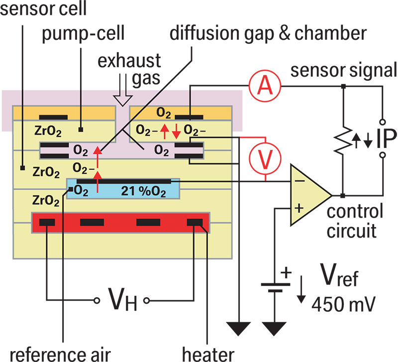
Further developments have occurred in the monitoring of exhaust gases. The United States and European governments have called for stricter and stricter regulations on reducing harmful emissions and increasing fuel economy, and rising fuel prices have put the issue of mpg right in the consumer’s face. To accurately control combustion and improve efficiency monitoring O2 content needs to happen sooner after start-up, for the rich mixtures present during warm-up, and for the lean mixtures of deceleration. Previous O2 sensors are not accurate enough, nor fast enough to provide a precise signal for these extremes. So, in the late 1990s a new technology was introduced known as the “wide-band†O2 sensor. This is still based on the Nernst principle, but there is now an additional chamber. Also, there are new sophisticated electronics within the control unit that allow it to take a more active role in monitoring the oxygen content of the exhaust gas.
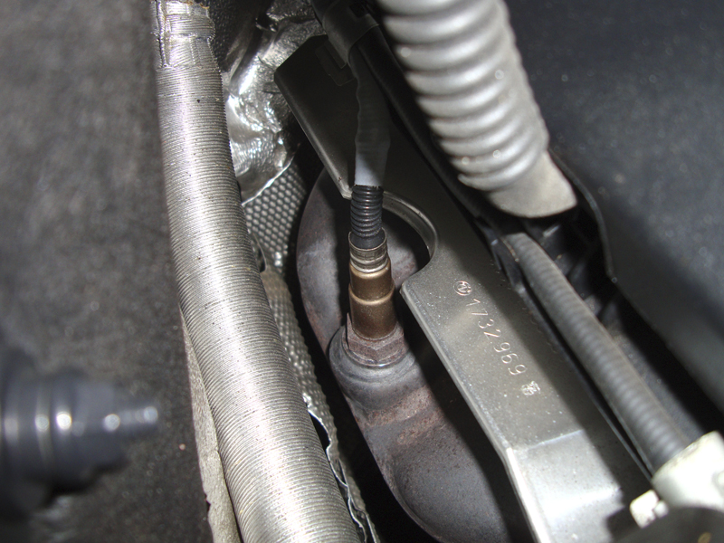
No longer are air/fuel ratio sensors mounted in the down pipe. They need over 750 deg. C. to function properly. Also notice how they are mounted straight up. This prevents condensation from getting trapped in the sensor, and it also makes service much easier.
Air/Fuel Ratio Sensor Operation
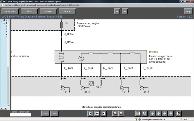
Through www.bmwtechinfo.com you can view the wiring of the air/fuel ratio sensor. Notice that there are six wires in the diagram, but only five on the sensor itself. That’s because you’re seeing the harness side of the connector.
The new air/fuel ratio sensor is still an oxygen sensor, but its new design allows it to start providing feedback after only 10 seconds! Not only is it fast, but it’s also capable of reading extremely rich and lean mixtures. As mentioned earlier, the sensor has two chambers. One is open to the atmosphere. This is known as the reference air gap, and is adjacent to the reference cell. This reference is always held at 450mv (Lambda). The other chamber is known as the diffusion gap or measuring chamber. This is adjacent to what is known as the pump cell, and is exposed to exhaust gas. The DME wants to maintain a stoichiometric ratio in the diffusion or measuring gap. As exhaust gases enter this gap, they are either high in oxygen (lean), or low in oxygen (rich). The DME reacts to these mixtures in the measuring gap by modulating the current to the pump cell. This in turn either attracts more O2 ions into the measuring gap (diffusion chamber), or repels the O2 ions from the gap. If the exhaust gas is lean the DME adds current to repel the O2 ions in the lean mixture out of the measuring gap. If the exhaust gas is rich the DME subtracts or pulls current to attract O2 ions into the measuring gap.
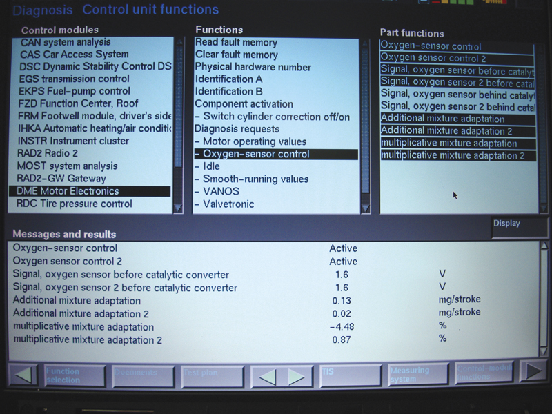
When using your scan tool, you may be tempted to watch the air/fuel ratio sensor voltage and make a determination from that. Here you see that both AFR sensors are reading 1.6 volts after opening the throttle, which you will not see on any wire at the sensor. This
show activity but not much else.
How does the DME know if the mixture is rich or lean? Remember, the DME monitors the reference cell and compares it to the exhaust in the measuring gap. The DME does not directly measure the difference between the O2 content in the exhaust and that in the reference cell. Instead, the DME monitors the amount of current it needs to add or subtract to the pump cell. The more current it adds, the leaner the mixture. The more current it subtracts, the richer the mixture is. The DME can add or subtract current very quickly to keep the ratiobetween the measuring gap and reference gap at the stoichiometric ideal. This translates into fast reaction time and the ability to monitor a broad range of mixtures.
The principle is similar to a Mass Air Flow sensor wherein the DME does not measure the temperature drop as air flows across the hot wire or film element. It monitors the current it adds to keep the wire at a specified temperature.
Symptoms?
You might think that its operating principles would make the air/fuel ratio sensor difficult to test. But like much of the new technology in today’s vehicles, there is more than on way to evaluate the sensor.
You can still measure the voltages from the sensor and watch how it reacts, but you can also directly monitor current to the pump cell. Of course, you can also use data from your GT1 scan tool, or factory software equivalent.
Whether the problem is a drivability complaint, a MIL on, or a failed emissions test, at some point you may need to test this new bit of technology. Before we get to actual procedures, we should mention some items of interest you should be aware of.
First, the reference cell must be exposed to the atmosphere. The outside air is supplied through the sensor connector and the harness. Any damage or contamination will result in the sensor not working properly, so be careful when using cleaning solutions and tell your customer to be aware of the potential problems engine compartments detailing can cause.
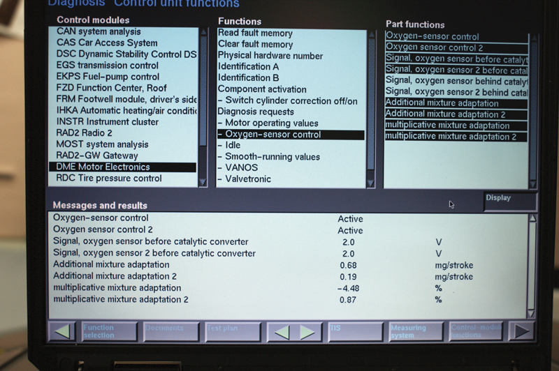
At a stable idle, you see 2.0 volts on the sensor, but this will not help you diagnose the problem. Look at “Additive Fuel Trim” and you see that the reading for Bank 1 is more than triple that of Bank 2. The multiplicative numbers show us Bank 1 is almost 5 times that of Bank 2. If injectors and coils are working properly, suspect the AFR sensor for Bank 2 as the source of the problem.
Next, these sensors only operate within a specific temperature range — approximately 750 deg. C is their working temperature. This is one reason they are mounted on the exhaust manifold where it is easier to maintain that level of heat. The sensors are almost always mounted straight up, too, which is necessary to allow condensation that would affect the sensor’s operation to evaporate out of the sensor body.
Another factor to consider is backpressure. These sensors are pressure-sensitive, which means a restricted exhaust system from a clogged catalytic converter will change the way the sensor responds. The flip side of this is the potential for improper operation presented by high-performance exhaust systems installed by a “tuner†customer. Changing exhaust volume, flow and backpressure characteristics can affect the way the sensor operates, so make sure you are not chasing your tail on this one.
As far as symptoms are concerned, you should know that the air/fuel ratio sensor has significant authority over the mixture, more than conventional O2 sensors had. They can certainly cause a drivability symptom as well as an illuminated MIL. Off-idle stumble, hesitation and surging can all have multiple causes, but the air/fuel ratio sensor is certainly a prominent suspect.
Testing
Testing these sensors can be challenging. Remember, they add and subtract current to change the polarity of the pump cell. To accurately read the mixture directly you must measure the current passing to and from the pump cell. If you remember “Basic Electricity 101,” you know that amperage is measured in series, which means you are going to have to open the circuit and connect your test leads to both sides of the pump cell circuit. The polarity of the leads also makes a difference. If you connect the positive lead of your meter to the harness side of the wire and the black lead to the sensor side of the wire, and the current is flowing from the DME unit to the sensor, you will register positive current. This would mean the computer is adding current to the pump cell as a reaction to a lean condition. If you reverse the polarity of your test leads, you would see the reverse and might mistake the negative current as indicative of a rich condition.
To indirectly test the activity of the sensor, you can monitor the voltage of the pump cell. You will not be able to tell if the mixture is rich or lean, but you will be able to see if the sensor is switching from rich to lean. This requires some advanced electrical testing. First, you need to connect the red test lead to the pump cell wire (the easiest access point is the sensor connector). You will notice that the sensor side of the connector has five wires in it, but the harness side has six! That is because the pump cell wire is spliced through a trimming resistor (mounted in the sensor side connector) into two wires. One continues on to the DME, and the other passes through the resistor and then goes to the DME. On the sensor side of the connector, monitor the voltage at pin #5 (the pump cell). This can be done with a graphing multi-meter or an oscilloscope. You should see just under 3.0 volts if you connect your ground directly to the battery. You can also use the sensor’s relative ground pin #2, which has about 2.5 volts on it. Since pin #5 has just about 2.9 volts on it, and the relative ground has 2.5 volts on it, you should see just under .5 volts on your meter. You will see a voltage swing plus or minus .25 volts if the sensor is reacting to changes in the mixture. As mentioned earlier, you are not directly measuring a rich or lean condition. You are only verifying that the sensor is reacting.
Another way that is a little less complicated is using additive and multiplicative fuel adaptation readings from scan data. Look at the additive numbers at idle. They should both read as close to zero as possible. If the value for one bank is different from the other, you can assume it is not a vacuum leak since that should affect both banks. Looking at the Multiplicative numbers, if you see that one of the percentages is not zero, but a few percentage points off, you can conclude that the problem is with one bank. This should also indicate that the trouble is relegated to one bank, and is not a problem with the MAF since that should affect both banks.
Knowing how air/fuel sensors work will allow you to accurately diagnose them. As with any new technology, aftermarket replacements are often reverse-engineered, which may take some time to get right. Genuine BMW original-equipment replacement air/fuel ratio sensors have the same strict quality control parameters as those that came with the car when new, and will go a long way in preventing comebacks.


0 Comments