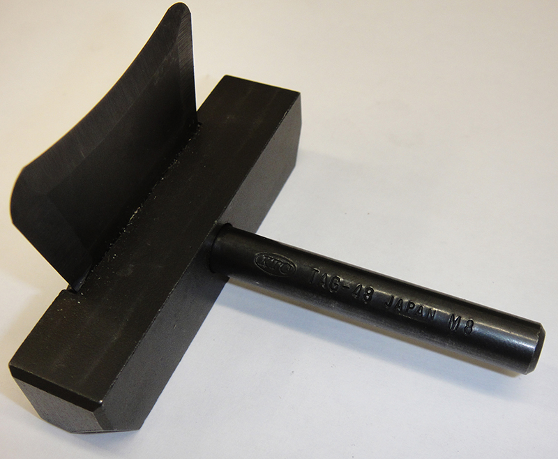
A seal splitter tool (SST# J37228) should be used to avoid damaging the timing cover during disassembly.
Timing chain service on Nissan and Infiniti vehicles can be both satisfying and profitable. Or, it can be a miserable experience that wreaks havoc on your time sheet and makes you wish you’d stayed home. It all depends on whether the job is performed correctly the first time. If you make an error, it may take hours or days to correct, but if everything is done correctly the first time, there can be a real sense of satisfaction in doing this type of purely mechanical work well, not to mention a very nice payday.
So simple a monkey could do it?
Timing chain service is not as simple as it once was. Older technicians will remember very simple timing chain designs: a couple of sprockets connected with a chain, channeled by a couple of guides, and held taught with a hydraulic tensioner. Ah, the good ol’ days.
Today’s vehicles aren’t so simple. Even a base-model Nissan will have four valves per cylinder, two cams per head, and variable cam timing. Because of this, the timing chain system needs to be more complex to keep the valves synchronized and the chain quiet.
Reading the instructions before starting a project is not a sign of incompetence. On the contrary, it’s a sign of a true professional. A minor mistake may require a complete repeat of the job, which can take more than a day on some models. A major mistake may damage the engine, leading to great expense indeed. Much of the necessary information will not be “obvious†from examining the timing chain before and during disassembly. Reading the manual is the only way to get all of the information you’ll need before you start.
Preparation
A technician’s efficiency of motion, focus, experience, and skill will all have an effect on how long a timing chain job occupies his service bay. However, waiting for parts to arrive will slow the progress of even the deftest technician. It may be impossible to predict every needed part before starting a job. On the other hand, if you have your local dealership email or fax you a copy of the exploded view, you can pick out and order all of the parts you know you’ll need for sure, as well as have the reference on hand to order any damaged parts you find on disassembly.
The coolant and the motor oil should be drained before starting timing chain service. Opening the block drain in addition to the radiator drain will reduce mess and help prevent coolant from entering the crankcase during the service.
Good light will save time and help avoid costly mistakes. Replacing a timing chain will take several hours – at the least. Working with a flashlight occupying one hand is just silly. Take a couple minutes to install a hood light or a couple well-placed drop lights. Not only will you be able to use both hands, you’ll be able to see things like the little glob of dried silicone you missed on the first cleaning, or the o-ring that fell out of position as you were installing the cover.
Many technicians have a powerful combination of memory and deduction. These “parts whisperers†are able to recall or deduce whether the yellow zinc-coated bolts were originally installed in the valve cover and the black oxide coated bolts were installed in the timing cover, or if it was the other way around. However, not everyone has this ability, and even those who do would benefit from the following suggestion: use a tray with compartments to organize bolts and small parts removed during disassembly. Even if you can restore the car to its original condition using a big pile-o’-bolts, it will take much less time if the bolts and small parts are grouped in sequence as they are removed, especially if the car ends up sitting for a week while waiting for customer authorization.
Getting started
This article will focus on the VQ series engine, a powerful and popular engine with variants found in the 350Z, 370Z, G35, G37, and Maxima.
The front timing cover and timing chain can be removed without removing the oil pan. If the timing chain is to be removed or the timing checked, the valve covers must be removed. If only the cover is being removed (to repair a leak for instance), the valve covers can be left in place.
There are a few parts blocking access to the front timing chain cover and valve covers, so they’ll need to be removed to gain access:
- The upper and lower intake collectors (they block the valve covers)
- The radiator cooling fan
- Drive belts
- The air conditioning compressor (leave hoses connected and tie off to the side)
- The power steering pump and bracket (leave hoses connected and tie off to the side)
- The by-pass coolant hose and the fan idler pulley bracket
Now that the way is clear, it’s time to remove the valve timing control covers, but wait! This is one of the procedures that can be costly if done incorrectly, but since you read the manual before starting, you already know that after using the seal cutter tool to break the RTV bond, you’ll need to carefully remove it by pulling straight back without tilting until it has separated completely.
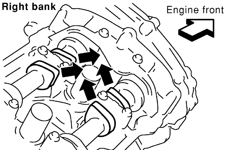
Next remove the valve covers and set the engine to TDC compression on cylinder #1 by lining up the TDC mark on the crank pulley. Then check the cam lobe position on cylinder #1 to verify it’s on the compression stroke. If the valves are in overlap (all 4 lobes slightly downward and touching the lifters), rotate the engine 360 degrees and line up the TDC mark up again, then verify the lobes are now pointing slightly upward and there is clearance between the lifters and lobes.
The crankshaft pulley is removed next. The engine will need to be held while the pulley bolt is loosened. If the starter is removed, Nissan special tool J44716 can be used to lock the flywheel in place. There are also commercially available tools that will work, although not as elegantly. DO NOT use a belt wrench or chain wrench on the outer crank pulley. Doing so may damage the harmonic damper.
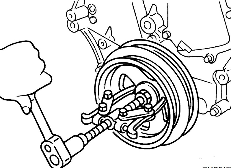
A standard two-jaw puller or similar tool can be used to remove the crank pulley once the bolt is loosened. Once again, do not apply any pressure to the outside of the crank pulley because it may damage the harmonic damper. Set the jaws on the inside of the pulley and set the puller drive bolt against the loosened crank pulley bolt head.
The timing cover is held in place by over 20 bolts. It is also stuck in place with dried liquid sealer. It will take some carefully applied force to loosen and remove the timing cover once the bolts have been removed. Therefore, it’s extremely important to be absolutely positive all of the bolts have been removed before attempting to remove the cover. The manual will have a diagram with the location and number of bolts holding the cover on. Count out the bolts removed before starting to pry.
The cover can be pried free using a combination of prying at two notches at the top of the timing cover, specially designed for that purpose, and working the seal cutter tool around the perimeter. Be very careful not to damage the sealing surface (or you could end up with a costly leak). Once the timing cover is off, store it with care. It is a fairly large and thin piece of aluminum, and can be damaged easily while unsupported.
Removing the chains and sprockets
The VQ series engines have three timing chains. A primary chain connects the crank sprocket to the intake cam sprockets and two secondary chains connect the intake cam sprockets to the exhaust cam sprockets. The primary chain has three guides and one tensioner. Each secondary chain has its own tensioner which drives a plunger guide against the chain.
The primary chain must be removed first because it sits in front of the secondary chains. To remove the primary chain:
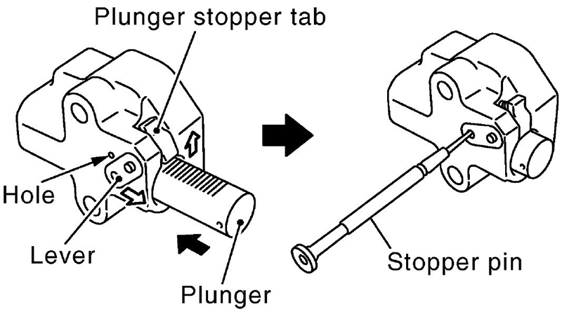
- Compress the primary chain tensioner by pressing on the ratchet release lever, then pushing the plunger into the bore. Once compressed, the plunger can be locked in place using an allen wrench or pin punch.
- Remove the slack guide (under the tensioner) and the internal guide (at the top of the chain).
- Remove the chain.
- Remove the tension guide.
It’s very important not to move the crankshaft or camshafts once the timing chain has been removed. This is an interference engine and the valves can be damaged by the pistons.
The secondary chains are removed with the sprockets. There is not enough slack to remove the chains with the sprockets in place. To remove the secondary chains:
- Compress the secondary tensioner and use a .020 in. (0.5mm) pin to lock it in place.
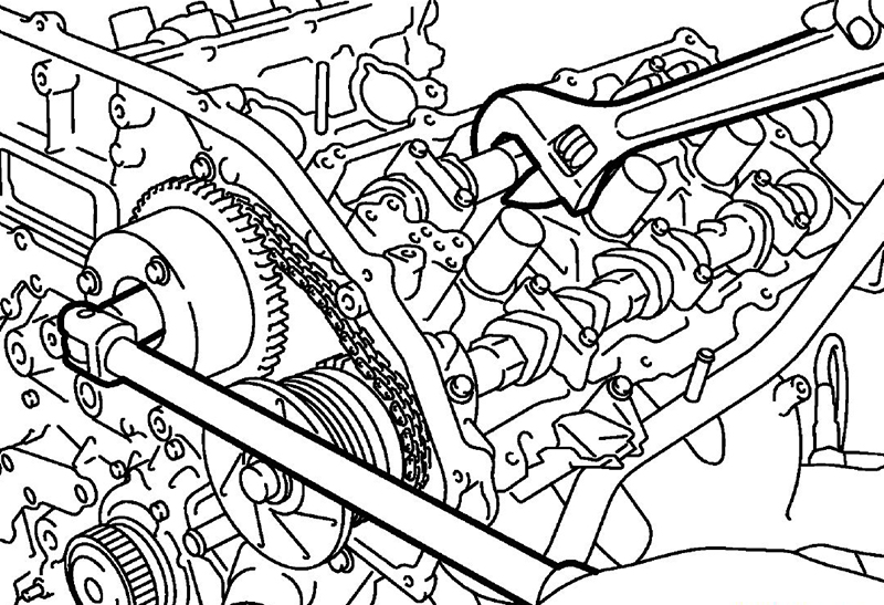
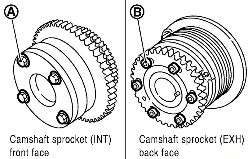
- Hold each camshaft using the hex portion cast into the cam near the mid-point (under the valve cover) then remove the center bolt for each sprocket.
Insert a thin piece of metal or plastic between the secondary tensioner guide and the chain. This will aid in removal of the chain by preventing it from getting caught in the groove of the guide as it is removed.
- Pull the sprockets and chain out together. Once the chain has cleared the tensioner guide, the guide may fall. Have a helper ready to catch the tensioner guide.
Inspecting and replacing
Check all components for damage and wear. When in doubt, it’s probably better to be safe than sorry and replace suspect components. The water pump is driven by the timing chain, so be sure to inspect for leaks and play in the bearing. The water pump can be replaced without removing the timing chain through a handy service port.
Installing the chains and sprockets
The secondary chains and sprockets are installed first. Verify the cams are still close to the original position. The dowel should be “up†on the exhaust cams, and the small hole should be “up†on the intake cams.
The back side of each sprocket has two stamped marks: oval marks and round marks. The correct position for the marks depends on whether the sprocket is used on the right (passenger side) bank or the left (driver side) bank.
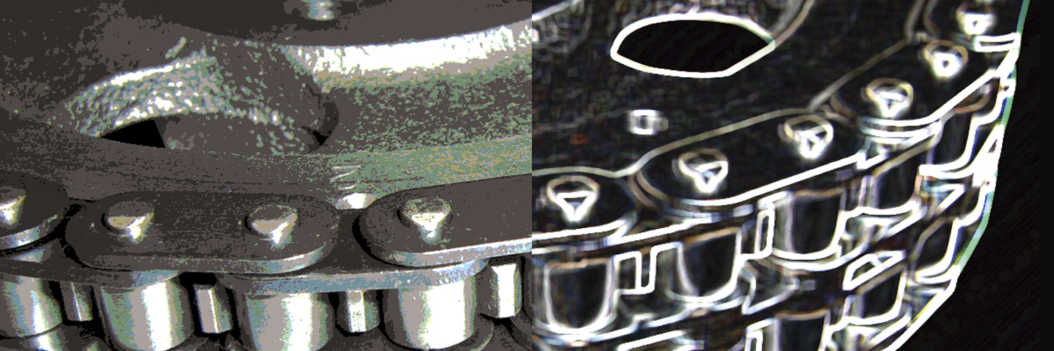
The secondary timing chains have three gold links, one by itself and two side by side. The single gold link should be lined up with the single mark on the intake cam. The side by side links should be lined up with the double marks.
If the sprockets are on the right (passenger) side, the round marks should be used. If the sprockets are on the left (driver) side, the oval marks should be used.
Because the marks are on the back side of the sprockets, they can be hard to see while installing the gears and chain. To make installation and timing verification easier, extend the marks over the top of the tooth or teeth with a paint pen before assembly.
Once the secondary chains are set up, install the primary chain. The tension guide (on the left side) and water pump must be installed before the chain. The crank key should be in roughly the 11 o’clock position, pointing towards the right (passenger side) cylinder head.
The primary chain also has colored teeth to aid in alignment. Two yellow teeth that line up with match marks on the intake cam sprockets and an orange tooth that lines up with the match mark on the crank sprocket.
It is possible to cause either of the secondary chains to jump time while installing the primary chain, so be sure to recheck both after the primary chain is installed.
It’s easy to make a mistake, so use the manual, and recheck your work several times. Take the time to be absolutely sure it’s right before moving on.
Cleaning and sealing
When used properly, Nissan liquid sealer provides an excellent long-lasting seal. However, to duplicate the original seal, you’ll need to recreate the original conditions. When the new engine was assembled, the parts were clean, there were no defects on the sealing surface, there was no dried silicone on any of the bolts or in any of the bolt holes, and the silicone was applied following the original design specifications.
- Use a small pick to check for and clean old silicone from bolt holes.
- Use a scraper and fine wire “toothbrush†to clean dried silicone from flats and corners.
- Use solvent that leaves no residue to remove oil, moisture and other debris.
- Follow the silicone application procedure in the manual. Don’t “wing it.â€
Sometimes it does matter which side of a bolt hole a bead is applied. Follow the schematics to avoid leaks.
Nissan does allow for the use of “equivalent†silicone sealant, but most quality sealants are roughly the same price, so why take a chance? Why not order a tube of Nissan Ultra Gray (PT # 999MP-AM003P) with your parts order. That way you’ll be sure that you have the correct type of sealer for the application.
While it’s not strictly necessary, the Nissan tube squeezing tool (SST# WS3993000) makes application in a uniform fashion easier and reduces wasted product.
There are also several gaskets, o-rings and seals that must be replaced.
- Verify the front crank seal is installed square, that the lip is not damaged, and the garter spring has not fallen off.
- Be very careful with the collared o-rings for the VVT system. Be sure they don’t fall out of place and get pinched on installation.
- Be careful the valve cover gaskets do not fall out of position during installation and become pinched. Also be sure to apply silicone to the areas noted in the manual.
Torque
Sometimes it isn’t possible to use a torque wrench on every fastener, at least not while the engine is in the car, but for the fasteners that can be accessed, using a torque wrench will reduce your chances of problems. You’ll find the torque specifications in the manual. Of particular importance are the cam sprocket bolts, crank pulley bolt, timing cover bolts, and valve cover bolts. The crank pulley bolt is the torque-to-yield type, so you’ll need an angle gauge in addition to a torque wrench.
Quality control
When the job is complete, double check all of your work. Run the engine at fast idle and check for oil and coolant leaks. Test drive to check for performance and abnormal noise.



0 Comments