
All manufacturers would like to design their engines to easily pass federal fuel emissions and efficiency standards and make enough horsepower to beat their competitors. Even automotive engineers have pipe dreams. In the past, General Motors has tried other forms of “Variable Displacement†as a way to maintain power when it is needed and reduce it when fuel economy is more important. In the early ‘80s the 4-6-8 Cadillac was a failed attempt at this. Cylinders were shut down to reduce fuel consumption when cruising with minimal load. The electronics of the time weren’t up to the task, however, and there were nothing but problems.
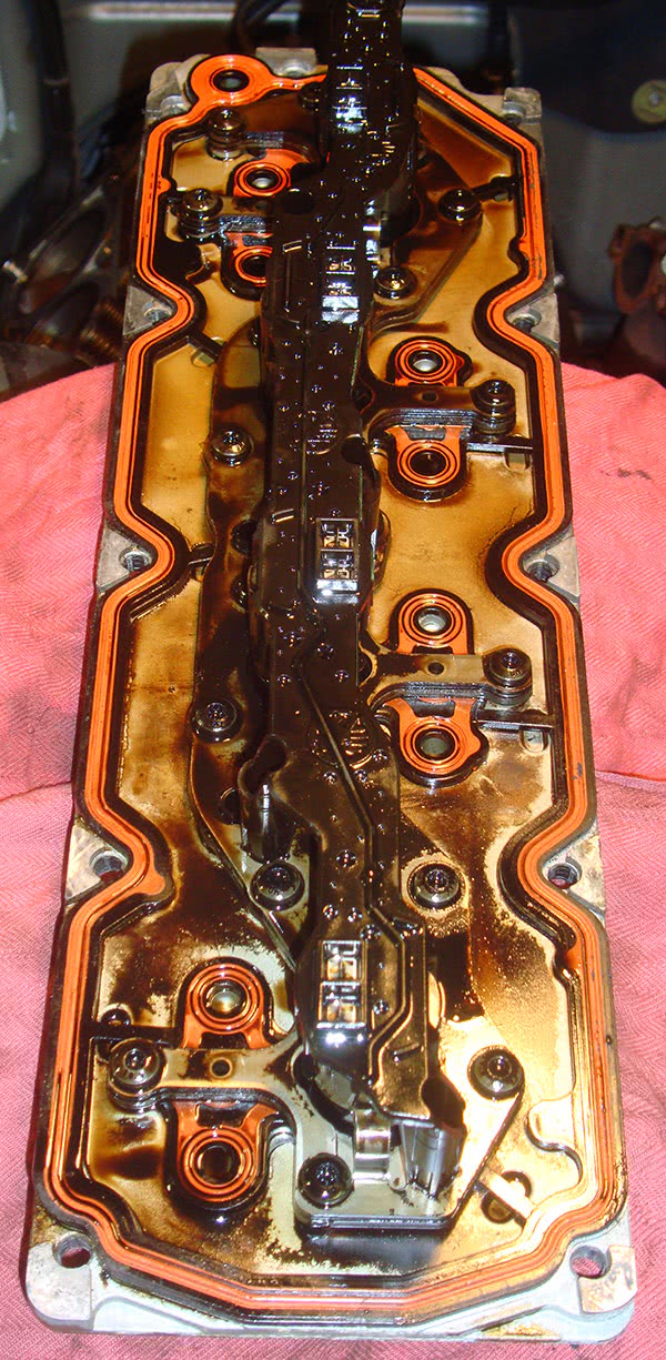
The heart of the variable displacement system is the VLOM (Valve Lifter Oil Manifold) assembly. It contains four solenoids that shut off oil to both the intake and exhaust valves of specific cylinders. It reduces mechanical “pumping losses†of the engine.
General Motors introduced the new 5.3L “M†engine (eigth VIN digit “0”) in 2005. It had a unique, innovative feature that reduced fuel consumption,and increased efficiency when not running on all eight cylinders by cutting oil flow to the lifters, allowing them to collapse and reducing valve lift to nothing. This meant the cylinder is not slowed down while drawing in the charge. The cylinder is only allowing the air inside to expand and contract, reducing compression losses. Finally, spent gasses are not stuffed into the limited volume of the exhaust system. All of this reduces what’s known as “pumping losses.†What are pumping losses, exactly?
“Sucking” in the charge, compressing it, and expelling it when spent takes horsepower. Of course, the twisting force generated during the power stroke is greater. Multiply this affect by number of cylinders and you understand why more cylinders make more power. But with more cylinders, you need to inject more fuel. When you shut off an injector, you reduce fuel consumption, but it still takes horsepower to put that dead cylinder through the four phases of an Otto-cycle engine, particularly on the compression stroke. By disabling the valve train, those pumping losses can be greatly reduced. It’s all about what’s called “volumetric efficiencyâ€. In the end, however, you don’t get something for nothing.
Variable valve timing has been around for decades. The idea is that oil pressure passes through an actuator, and a solenoid is used to close off the return flow. As the pressure builds in the actuator, it changes the relative position of the intake and/or exhaust camshafts, thus moving the engine’s volumetric efficiency to another rpm range. This produces noticeable improvements in engine performance and efficiency, but there is a price to be paid when things are not going right. The trapped oil tends to produce sludge, especially when oil change intervals
aren’t adhered to.
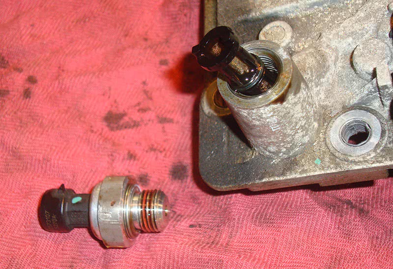
In the back of the VOLM, you’ll see the oil pressure switch sticking up. Under it is a filter screen. Remove it and see if it is clogged. Lack of timely oil changes?
The same thing can happen on any system that relies on oil quality and pressure to perform correctly. This is why proper oil change intervals are especially critical on today’s engines. When you have variable valve timing or a variable-displacement/lifter function, one of the first steps you should take is to check the last time the customer had an oil change, oil type (mineral or synthetic), and the oil level. Although trouble codes are helpful in diagnosing a problem, they will probably not help you with a lifter tap other than showing a misfire code for the offending cylinder. Changing a noisy lifter may fix the problem, but only temporarily. That lifter can fail again if allowed to run dry due to clogged oil passages.
The way General Motors engineers developed this engine was to only disable certain cylinders: #1, #4, #6 and #7 (By the way, bank #1 is on the driver’s side, and the firing order alternates from side to side). If you have a misfire on any other cylinder, it can’t be caused by the cylinder shut off solenoid, although you can have lifter problems just like in any other cylinder.
Since the variable displacement system is dependent on oil pressure it is important to know how the oil is supplied and controlled. Never before have I seen such detailed oil pressure specs from GM. At minimum, there must be six psi at idle, 18 psi at 2,000 rpm, and 24 psi at 4,000rpm. The pump is of the radial type mounted on the front of the block around the nose of the crankshaft. It supplies oil to the crankshaft first. Coming up from the back of the block on the driver’s side of the lifter valley is the oil supply to the lifters. It passes through a filter screen in the valley cover. This cover has passages that direct the oil through solenoids downward into the block and onward to the lifter bores. It is referred to as the VLOM (Valve Lifter Oil Manifold) assembly. Remember, this is only for cylinders #1, #4, #6, and #7. All other cylinders lifters are fed directly through passages in the block, not the lifter valley cover.
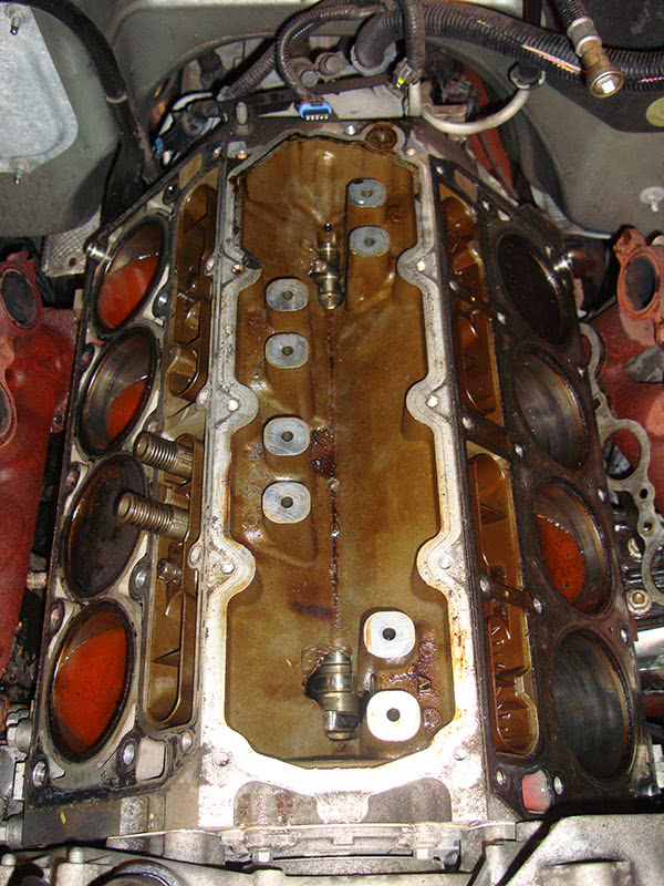
The bosses sticking up from the lifter valley area are the passages that supply oil from the VLOM to each cylinder. Notice how they are only for cylinders #1, #4, #6 and #7. While you’ve got it apart, make sure the passages are clear.
The cylinder shut-off solenoids are mounted in the VLOM, and are controlled by the PCM. When the PCM grounds a solenoid, it cuts oil flow to the intake and exhaust lifters for that cylinder. When the cam lobe comes around to push on the extended-length lifters, they collapse and neither valve will open. The injector is also shut off to that cylinder. When the solenoid is de-energized, oil flow is restored to the lifters and they quickly pump up and start opening the valves.
Obviously, the misfire monitor is suspended for each cylinder that is disabled. It is turned back one when the cylinders are reactivated. If the lifter stays collapsed even though the solenoid is de-energized, a misfire code is set. You may hear the obvious lifter tap, but it depends on what position the lifter gets stuck in. Instead of a complete failure, you may only have limited valve lift, which can lead to a misfire without the tapping noise.
Whenever you are presented with a misfire to diagnose, you have to decide where to begin. You should check for injector pulse with a noid light, and use your high-kV spark tester to verify that the cylinder has fuel and fire. Another old trick is to spray starting fluid into the intake and crank. If it starts momentarily now, you know fuel is the problem. You’ll should also pull a plug and check it. Don’t just throw a coil at it and see what happens.
In the old days, it was simple. You would put a vacuum gauge on the intake manifold and watch the needle bounce. Very few people know how to read a vacuum gauge anymore, and the one on your manual vacuum pump is not accurate enough for engine pumping diagnostics — the needle will bounce even with a normal engine. You need to use a real engine vacuum gauge. This may tell you that there is a problem with pumping, but you still need to find out which cylinder is at fault. You can use the misfire monitor on your scan tool, or, better yet, do an old-fashioned compression test on each cylinder and compare readings, and perhaps perform a dynamic compression test as well.
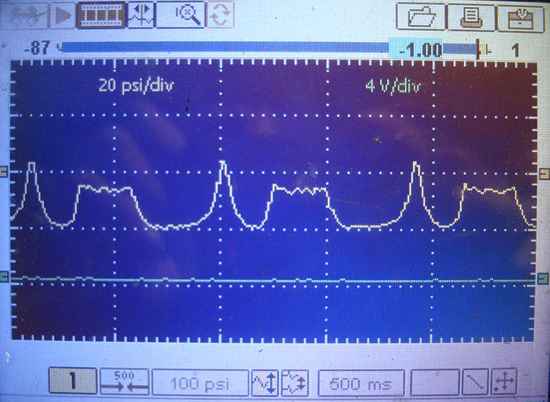
If you have a pressure transducer, you can compare the misfiring cylinder to a good one and see if you have the same pattern. You should be able to determine if it is a sticking intake or exhaust lifter.
If you have invested in a pressure transducer and an oscilloscope, you can get a picture of the pressure in the cylinder. This can help you isolate if the problem is with the intake or exhaust valves. If you are somewhat more sophisticated, there is software out there that allows you to tap into the intake manifold to measure the intake pulses with your transducer and match it to the firing order to isolate the cylinder. That is another in-depth subject that would take up an entire article itself, so we will leave it for another time. Looking at the pressure reading in the cylinder, you can see if the intake and/or exhaust valve is not opening.
A conventional compression test, a “running†compression test, and monitoring the signal voltage from a pressure transducer are all good for determining if a cylinder is working properly. If you are doing a regular compression test, remember you should only crank the engine about five pulses of you gauge. With a running compression test you can simply hold down the pressure release button on your gauge and watch for the peak as the needle bounces. Of course, you know to compare problem cylinders with good ones. A tool that may be new to you is the pressure transducer. It converts the pressure reading inside the cylinder into a signal voltage that you can view on a DMM, or, better yet, a graphing multi-meter or oscilloscope.
In our 5.3L we found that #4 cylinder was misfiring. We could clearly hear the lifter tap, but chose to test the cylinder anyway to make sure we verified that the problem was in the valve train. On this engine, it is important to know for sure since you will need to remove the cylinder heads (!) because the overhang of the head covers the lifter housing. It would be a good idea to change all of the lifters or at least the ones that can shut down a cylinder. Look at the pressure transducer voltage pattern in our example and you’ll see a low-voltage peak during compression. The pattern starts with the relative flat horizontal line indicating atmospheric pressure followed by a drop in voltage from the vacuum of the intake stroke. The low compression spike is next and finally the exhaust pulse.
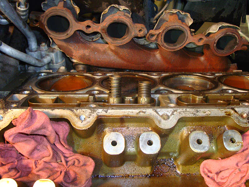
Here’s the collapsed intake lifter for the #4 hole. This was a severe one with the lifter being completely stuck in the compressed position. The cylinder heads need to be removed to fix it.
The intake valve lifter for #4 cylinder had collapsed. The pattern shows what happens when the intake valve doesn’t open and the exhaust does. It’s why you see the drop in voltage indicating vacuum after the compression stroke when you should see exhaust pulses, which are much closer to atmospheric pressure. Okay, the heads are coming off and there is the necessary discussion with the customer about how we should replace everything while we are in there, and also on the importance of oil changes with these new sophisticated valve trains. Synthetic oil and additives such as moly, (molybdenum disulfide) is a dry-film lubricant that will keep the lifters slippery even after the oil supply is reduced for cylinder cancellation. The customer is not going to be happy, but we think we’ll see him sooner rather than later for the next oil change.
by Kerry Jonsson


0 Comments