

 BMW owners expect a lot from their vehicles. From the moment of purchase, they were treated to technological advancements they may not even have noticed. The operation and integration of systems was so seamless that they took all this wizardry for granted. The driver utilized the navigation system, the passenger changed stations on the satellite radio, and others in the back were entertained by the latest DVD. And all of this was being controlled through the MOST (Media Oriented System Transport) bus.
This is different from all other bus systems in that it does not use pulse-width modulated electrical signals across a wire. MOST uses light pulses traveling across fiber-optic cable to transmit and receive data. Fiber optics have been around for many years and has proved successful in transmitting large amounts of data very efficiently.
Why Fiber Optics?
CAN systems have been in automotive use since the mid-’80s. They are communication lines that carry digital square wave signals along a wire from one control unit to another. With a CAN, numerous computers can share information with one another instead of having multiple separate sensors doing the same job for each control unit. This reduces the number of sensors and wires, and the overall complexity of a vehicle. A huge amount of data gets passed around on a CAN.
Today, instead of a few control units on the network, there are many. And wires carrying signals are prone to interference from other wiring. Remember, as electrical current flows through a wire it generates a magnetic field. If the field is strong enough, it can interfere with sensitive data-line communication. In contrast, fiber optic cable carries a wave of light, which is not affected by the electromagnetic fields of any wires.
Light Beams for Automotive Use

In order to communicate through the fiber-optic network you need to access the diagnostic connector. On the 3 – Series vehicles the connector is mounted behind a cover by the hood release handle. On the 5 and 7 – Series it is mounted in the upper panel of the glove box.
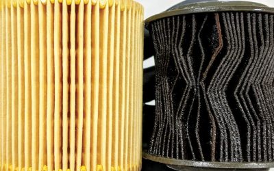
The type of fiber optic cable used in your community’s communications infrastructure is made up of glass fibers. These installations are permanent and isolated from vibration. If fiber optics are to be used in automotive applications, a cable is needed that can handle temperature extremes and vibration. Dow-Corning developed a polymer fiber optic cable that is well-suited for automotive use. Small amounts of dust to not interfere with the data transmission, and the cables can be installed within the tight confines of a vehicle body. They can be routed with a wiring harness without any worry of electromagnetic interference and can handle a large amount of data. This is not to say fiber optics do not have limits. The longer the light has to travel through a cable, the weaker the signal becomes. This is known as attenuation, the loss of signal strength.
This loss of the signal strength can be caused by several factors. Any sharp bends less than two inches in diameter will impede a signal, and a kinked cable will cause interference. A crushed cable will distort the light signal, so be wary of this on vehicles with body damage. If the cable is stretched in any way it will result in corrupt data transmissions. Excessive dirt or grease on the cable tip, as well as scratches on the cable ends will distort the light signal. Also, watch out for damaged insulation. The fiber optic cable has an internal sheathing as well as a cover that keeps the signal from refracting outwards, therefore ruining it. The general rule is to avoid any undue stress on the cables when tugging a wiring harness in the process of repairing a vehicle. Even a small, temporary stress on the cable can cause communication problems, and affect the whole system.
The Layout of the MOST bus
If you are familiar with communication networks, you probably know that BMW CAN systems use the Bosch CAN two-wire parallel setup. Each control unit has two wires for the CAN. One is CAN High and the other is CAN Low. The CAN High signal starts off close to ground and pulses upwards. The CAN Low signal starts off at a higher voltage and is pulsed downward. The two signals mirror each other and carry the same information. This way, if one line goes down the control units can operate on the other line. To put it another way, the control units are wired in parallel so if one unit fails the others can continue communicating.
There are multiple CANs for the different systems of the vehicle. There is the Powertrain CAN, Chassis CAN, Diagnosis CAN, and FlexRay CAN, depending on the year, make and model of the BMW you are working on, and they may be connected together through a central gateway computer.
The MOST bus system is different. It is not connected in parallel. Since it is passing a light transmission, the signal has to have a starting point and an end point. The starting point is referred to as the master or multi audio system controller. All the control units on the MOST bus can pass information, but only the master can share communication with other bus systems on the car. A ring structure is used to connect the control units on the bus. This means the signal originates from the master control unit on the “transmit†cable and is sent to the second control unit to the “receive†terminal. Each control unit has a “transmit†and a “receive†terminal (two fiber optic cables). Terminal 1 is always the “receive†terminal or input cable, and terminal 2 is always for the “transmit†or output cable. The output cable of the first control unit is sent to the receive terminal of the second, and so on.
Can You See the Glow?
To ensure a strong light signal, the second control unit copies the signal and retransmits it. This is done until the control unit the message is sent to receives the signal. Each control unit on the MOST can send a signal to the others; it simply may have to pass through other control units in the process. The corresponding cables form a ring between each of the control units. This also means if the ring is broken, the system will not function. It a control unit is not powered up, the fiber optic input and output cables are connected together. This allows the signal to pass through it to allow the rest of the system to keep working. However, if there is a malfunction in a control unit the signal will stop there and all of the MOST components will not work. You will need to identify which control unit is in trouble to fix the problem.

By visiting www.bmwtechinfo.com you can access ISTA for service information. You can pull up a MOST bus fiber optic cable diagram. This lets you know what control units may be in the vehicle you are working on and where you have to check for the fiber optic signals.
What Happens When it Stops Working?
Manual ring break diagnosis is quite simple, but it does require a bit of labor. You are going to have to pull up a diagram of the MOST bus components. Each vehicle is going to be slightly different depending on the chassis layout of the MOST bus and the options the vehicle came with. You can start at the beginning of the MOST circuit, or at the end. Simply unplug the fiber optic connector and look at the receive terminal. You should see a red blinking light. This light’s frequency is 650 nanometers, which is the frequency of red light. An LED, not a laser, is used to generate the signal, so it is safe to look at directly. If the red light is not visible, you can reconnect and move to the next component in the loop. Keep doing this until you reach the control unit that is not emitting a signal.
The More Things Change . . .
Another way of approaching the diagnosis is to unplug each control unit and install a connector loop. This component is found in the glove box of the E65/E66 7-Series vehicles connected to the diagnostic plug for the fiber optic adapter. You can purchase these fiber optic loops from you BMW dealer’s parts department. The connectors are standardized, so you can plug in your loop to bypass any component on the MOST bus. Also, you can use your iComm/iSTA software to find out which options the vehicle has. The MOST bus components are assigned a node in the master control unit, and you can look at a list of installed components. Although many BMWs have SAT radio, some customers did not order that option at the time of purchase so their vehicles will not have a SAT radio receiver.
By the same token, if a customer added an optional system down the road you will have to use iComm/ISTA to program the multi-audio master control unit to accept the change before the component can become operational. The MOST bus is flexible in that a car owner can add new MOST bus components without the worry of overtaxing the system. BMW provides additional fiber optic cable already in the vehicle for this very purpose. You can connect a retrofitted component to an existing plug for an option that is not installed, but you still need to let the master control unit know. Also, when replacing a component you are going to have to code it to the vehicle. On the MOST bus, this requires a few steps. Every component on the MOST bus must coded for the new or additional component. Denision and MoBridge are two aftermarket companies that provide MOST bus components that can be programmed into the system.
What to Do When Things Go Wrong?

As a preliminary check, you can unplug each component and look for a blinking red light signal while the MOST bus is active. If you unplug a component and the cable is not blinking, do not blame the component you unplugged, but the one the signal is coming from.
When the system goes down, it usually means one or all of the components are either not functioning or not powering up. This can be caused by any of the individual control units on the MOST bus. Picture the MOST system as a single control unit with multiple power supplies and grounds. The system can also be shut down if one of the components reaches 160 deg. F. (70 deg. C). The overheated unit will shut off and take the system with it. Through the Service menu, you can use the display panel to call up all of the components that are installed on the vehicle if the optical ring is functional. Each of these power supplies and grounds must be there to get the entire system operational. If only one is missing, the whole system will not work. A visit to www.bmwtechinfo.com can provide you with the necessary wiring and fiber optic diagrams so you can follow the power supply.
As an example, on the early E90 chassis the power supply for the CCC/M-ASK module, which wakes up and controls the MOST bus, comes from the bi-stable relays mounted in the junction box control module. With BMW iComm/ISTA, you can activate these relays on and off while testing the power supply at the CCC/M-ASK module mounted in the center console. On early E60 chassis 5-Series vehicles that do not have a KGM Body Gateway Module, the power supply comes from a Micro Power Module mounted in a styrofoam insert under the spare tire. The Micro Power Module has two constant power supplies (terminal 30) and one ignition-on power supply (terminal 15). It is on the K-CAN, which tells it when to power up fuse #34 that powers up the CCC/M-ASK unit. On a 7-Series (E66 Chassis), the MOST bus Audio System Controller is powered up by the Power Module through fuse #65.
Early 7-Series

You can order a 7–Series fiber optic loop from your local BMW dealer’s parts department. This can be plugged into the fiber optic harness plug to bypass the component you believe to be the problem.
The difference with the early E66 chassis is that the MOST network is connected to the Instrument cluster and Control Display. You can enter these control units through the K-CAN to run a quick test and see if you have codes informing you that the MOST is down. Problems in the electrical system (low voltage supply) will tell the Power Module to shut off unnecessary accessories to conserve amperage. The iComm/ISTA diagnostic tool is critical to system diagnosis once voltage supplies have been checked.
After that, it comes down to manual ring break diagnosis. As mentioned earlier, this means going to each control unit in order and checking for the red blinking light. MOST fiber optic cables can be repaired with one terminal connection per line before the signal is in danger of becoming distorted. The ByteFlight system is also fiber optic, but since it is safety-related no repairs are allowed to any of the cables. They must be replaced.
The MOST bus fiber optic system is complex, but if you break it down to its essential components you should be able to get through diagnostics with a wiring and fiber optic diagram. Be prepared to check powers and grounds at multiple control units, and check the light signal at each component. This can be labor-intensive, but you will eventually find the solution to your customer’s problem. This is the kind of effort that keeps your customers coming back to you for service.

If you look at the diagram, you will see that the fiber-optic signal originates from the Audio System Controller. The next stop is the instrument cluster, and after passing through the loop and the Amplifier, it returns to the Audio System Controller.
Hi very informative and thank you. I have just purchased a 2010 BMW 116D sport. It has a mulf2 high basis svs module in the trunk(Bluetooth Logo). Connected to the module is a blue plug and a black plug containing the fibre optics cable.There is also a black coaxial connected to a aerial point. The head unit is a BMW professional unit (s663) connected to this at the rear is the fibre optics cable.When removed from the radio, it emits a red flashing light.(which if plugged back in the radio and checked from the mulf unit it does the same) I assuming that this informs me that my optic cable is ok. My question being is that I have no telephone icon for blue tooth on the head unit.(has BMW logo). I do need to attach a mic to the mulf and a Bluetooth aerial on the yellow socket.
Please could you advise me why the head unit is not registering blue tooth functions.