Secondary air systems are designed to help the catalytic converter get up to operating temperature faster. When the system develops a problem, the ME control unit is capable of defining the fault. It’s our job to figure out the cause.
The internal combustion engine has been with us for a very long time, and although electric motors are being designed into more and more vehicles battery technology needs to improve before the buying public is convinced. This means hybrids are a more viable choice, but they still need a generator. A gasoline engine can be used to generate electricity and also provide power directly to propel the vehicle down the road. But neither is anywhere near 100% efficient. Much of the energy produced by combustion is still lost as heat, which is why we have a cooling system. We have the same problem with combustion itself. Atmospheric pressure fills the cylinders and we inject fuel to create a burnable mixture. This is then compressed until it is on the verge of igniting. We then add a spark at the proper time and the combustion process begins. As the gases expand, they push down on a piston that turns a crankshaft and power is produced. This process is not perfect, however.
We Can Only Strive for Perfection
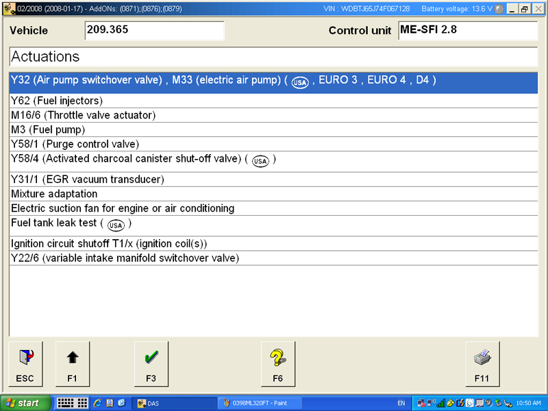
With an SDS, you can enter the engine control unit and command the secondary air injection test. Here, all of the hard work is done for you. The air pump and air injection solenoid are activated and fuel trim information is displayed so you can see if the system is functioning properly.
In an ideal world, the internal combustion engine would convert the air/fuel charge into carbon dioxide (CO2), oxides of nitrogen (NOx), and water (H20) as a result of the combustion process. This is not an ideal world. Hydrocarbons (HC) are not completely burned, and carbon monoxide (CO) is formed from incomplete combustion. These gases are toxic. As a result of the Clean Air Act of 1970, and its later manifestations, greater and greater efforts had to be made to reduce these harmful emissions that came out of the increasing number of cars on the road.
Various anti-pollution devices were fitted to vehicles. Fuel vapors (HC) have to go somewhere, preferably not into the atmosphere, so we got the evaporative emissions system (EVAP) with its charcoal canister to store these vapors until they were burned in the cylinders. But something needed to be done about the byproducts of inefficient combustion exiting the tailpipe.
In 1975, automobiles sold in the U.S. were required to have a catalytic converter fitted in the exhaust system. This converted raw HC and partially-burned CO into CO2, NOx, and H20, significantly reducing harmful exhaust. Early catalytic converters were only two-stage (HC and CO), but about 30 years ago, the three-stage type appeared in an effort to control NOx emissions. Lean mixtures lead to high combustion chamber temperatures, which increase the formation of NOx. EGR (Exhaust Gas Recirculation) recycles inert exhaust gases into the intake manifold, diluting the mixture and cooling the fire to cut NOx production, but it couldn’t do enough. The three-way catalytic converter has a reduction section upstream of the oxidation section, which when combined with a closed-loop fuel system, breaks NOx down very efficienly. We should mention right here that the washcoat on the ceramic honeycomb contains precious metals such as cerium, rhodium, palladium, and platinum. This is why high-quality OEM replacement converters are so expensive. Cheaper aftermarket replacements do not contain the proper quantities of these precious metals, so do not work as effectively, or for very long.
Cleaning Up the Air
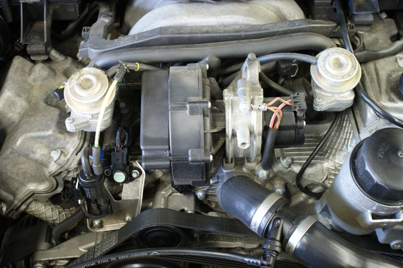
The modern secondary air pump on this 112/113 engine is mounted in front of the intake manifold so heat will evaporate any moisture that has condensed in the lines. It also makes manual testing easy. To the left of the pump is the air injection solenoid, and on the upper left and right are the air injection valves.
The function of a catalytic converter is not limitless. You cannot have an extremely rich mixture in your exhaust and expect the converter to clean up all of the exhaust gas. The NOx reduction section of a modern catalytic converter is designed to work with a 14.7:1 “stoichiometric†air/fuel ratio. In the days of carburetors, mixtures were set by means of adjustments, or relatively crude jet sizes. When fuel injection with feedback appeared, it became possible to achieve and maintain this ideal blend.
One of the important characteristics of a catalytic converter is its ability to store oxygen. During lean conditions there is excess oxygen in the exhaust stream. This is stored on the surface of the substrate. In the exhaust stream the oxygen sensor reads this lean condition and switches to a slightly richer condition. During this rich condition, the converter gives off the oxygen it has stored to oxidize the HC and CO passing by.
The oxidizing process requires plenty of heat, and a catalytic converter needs to be in its optimum temperature range to function properly. This means oxidation doesn’t occur immediately after the engine is started — it takes a certain amount of time for the exhaust to heat the catalytic converter up to operating temperature. During this warm-up period, the exhaust stream contains the highest quantity of harmful emissions. Stricter and stricter regulations are being implemented by the government every year, so manufacturers must come up with ways to meet these guidelines. This includes reducing the harmful emissions released during the converter’s warm-up period. Although it has been around since the ‘70s, air injection is still one way to reduce HC and CO while the converter is reaching operating temperature. Oxygen-rich fresh air is pumped into the exhaust stream to help burn HC and CO. Early air pumps were belt-driven off the engine, but modern Mercedes-Benz vehicles use an electric pump. The pump only comes on for the first few minutes after the engine is started, and serves no real purpose during the rest of the drive cycle.
Injecting Air into the Equation
In this system, the fresh air is aimed at exhaust ports as close as possible to the combustion chamber to start the oxidizing process. Even though the rest of the engine and the converter are still cold, the exhaust gases are instantly hot and adding oxygen at this point helps complete the combustion process of HC and CO. The extra heat generated in the exhaust stream helps to rapidly raise the temperature of the catalytic converter to its operating temperature.
The electric air pump is only turned on in two instances. The first is when the engine is in the warm-up phase, and the second is when the ME control unit wants to check the system. It activates the air pump and the secondary air valve solenoid while the engine is fully warmed up. At this point, the oxygen sensors are working to control the mixture. By pumping in fresh air, the ME can monitor the oxygen sensors and verify that they indicate a lean condition while the secondary air is flowing.
Whenever you pump air, you compress it. This condenses the moisture in the air. This can work its way in to the air pump motor causing it to fail prematurely. For this reason, Mercedes-Benz has chosen to install the air pump in a hot environment, which helps the moisture to evaporate while the pump is not being used. Typically, pumps are mounted on the front of the engine, just in front of the intake manifold, or on the passenger side of the block, toward the front of the engine.
Mercedes-Benz pumps are supplied voltage directly by a secondary air pump relay. They draw in the range of 25 to 30 amps, so it is important to verify that you have a good relay. Voltage drop across relay contacts can reduce available voltage, thereby increasing the amp draw. This can lead to blown fuses or premature pump failure. If you need to replace a pump, you should always replace the relay as well.
Controlling The Flow
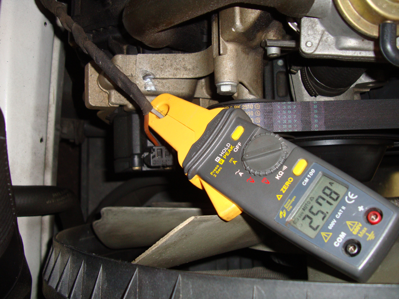
You should measure the amperage draw of the pump if you have found a blown fuse for the system. Normal draw is between 25 and 30 amps. Higher than that and the pump may be seizing. Any lower and the pump may be worn and not be producing enough air flow.
When the pump is working, it supplies air through tubes to the secondary air injection valves. These vacuum-controlled valves allow the air into the ports cast into the cylinder head that lead to the exhaust ports. A secondary air injection solenoid is switched on by the ME control unit. The solenoid supplies vacuum to the air injection valves to open them. There is also a reed valve mounted underneath the air injection valve. The pumped air can push the reed valves open to allow the air to continue on to the exhaust ports. Once the pump stops, the reed valves close, preventing hot exhaust gases from backing up into the air injection control valves. Also, the ME control unit de-energizes the air injection solenoid. This blocks vacuum to the control valves allowing them to close. This further prevents exhaust from getting into the pump. When the system is working properly, you will notice the air pump come on after a few minutes and run for up to two minutes. You may also notice the system check itself after an extended idle.
To test the system, the ME control unit monitors the oxygen sensor signal voltage. With the air injection system pumping fresh air into the exhaust ports, the O2 sensor reads the false lean condition. The ME control unit will try to compensate for this by increasing injector pulse width. The fuel trim readings will indicate this increase in fuel injector on-time. If you watch the fuel trims while the test is happening, you will see the additive fuel trim go up to 25%. If the fuel trim does not increase enough, the ME will set a code P0410. It is your job to determine which part of the system is not functioning properly. You can access a wiring diagram with a paid subscription to www.startekinfo.com. If you have invested in a Star SDS system, you can test the system dynamically. You can monitor the data while the SDS puts the ME control unit into the secondary air test. Watch the Additive fuel trim readings while in the test and verify they increase over 25%.
If You Have Manual Control
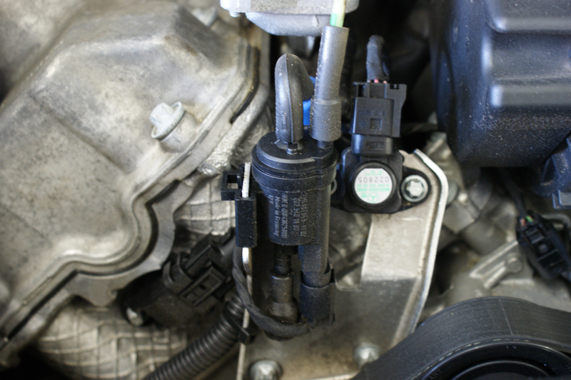
The air injection solenoid supplies the vacuum it gets from the intake manifold to the air injection valves. It is only energized when the engine is in the warm-up phase and when the monitor runs. If the solenoid malfunctions, the valves will not open and pumped air will not make it to the ports.
If you have to perform the test manually, there are a few steps you need to do before you can complete the test. First, you have to activate the secondary air pump. You can do this by locating the pump relay, then you can either apply a ground to the relay, or simply jump past the switched contacts. These are always terminal 30 (DIN for constant power) and 87 (DIN for relay output). You should hear the air pump come on and feel air being pumped out toward the air injection valve. You should also measure the voltage to the pump and its amperage draw. As mentioned earlier, poor relay contacts will drop the available voltage supply to the pump. With low voltage to the pump, the amperage draw has to increase, which can electrically overheat a pump until the fuse for the relay blows. If you get the pump to run, you now have to activate the secondary air injection solenoid. You can back-probe the ground side of the solenoid and apply a temporary ground. You should now measure vacuum to the secondary air injection valves.
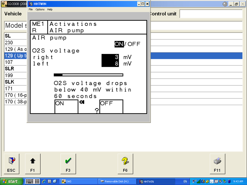
On older vehicles, the HHTWIN system can allow you to dynamically test the secondary air system. Here the pump and solenoid are activated and the SDS displays the oxygen sensor signal voltage to verify that pumped air is making it into the exhaust stream and creating a false lean condition.
The valves should be open at this point. If you remove the air injection supply hose, you should not feel exhaust gas coming out of the open end of the valve. The reed valve mentioned earlier should be held closed blocking exhaust gas from coming through the valve backwards. If you feel exhaust gases, you will need to remove the secondary air valve and inspect the reed valve to see if it is damaged. While you have the valve removed, you can apply vacuum to it with a hand pump and see if the valve opens mechanically. With the air valve and reed valve removed, the secondary air injection ports are exposed. If you run the engine you should feel exhaust gas flowing out of the ports in the cylinder head. If you do not, the ports in the cylinder head are blocked. The proper repair for this problem is to remove the cylinder heads and clean out the secondary air ports, although there may be alternative means. At this point, you have checked the operation of the air pump, injection solenoids, injection valves, reed valves, and cylinder head exhaust ports. If everything is in order, you can check the system dynamically.
Working On Your Own
You can use a generic scan tool to monitor the short-term fuel trim while the engine is running. If you have a Star SDS, you should monitor the additive fuel trim. Now, activate the pump and secondary air solenoid and watch the fuel trim readings or watch the oxygen sensor signal voltages. The O2 sensors should drop to under 100 millivolts indicating the lean condition. The short-term fuel trim should increase to 20 to 25% while the pump is running. If the percentage is not changing enough, you will need to determine if the passages are clogged or the air pump output is too weak.
A properly functioning system should have an easy time passing the OBD II monitor providing the oxygen sensor monitor has already run. If you’ve performed diagnosis and repair properly, you have provided the level of service your customer expects from you. You have helped reduce harmful emissions from the engine exhaust and helped assure that the vehicle will pass state or local emissions inspection. That should lead to a happy customer. Â
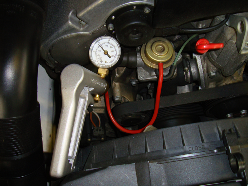
Here we are manually applying vacuum to the secondary air valve. The valve should hold vacuum. If not, the valve’s diaphragm is torn and the valve needs to be replaced. You should activate the solenoid and verify vacuum is making it to the valve as well.


0 Comments