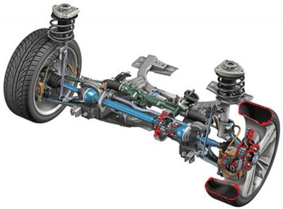
Many advanced steering, stability control, and propulsion technologies in the front-drive CLA depend upon precise suspension geometry for proper vehicle operation. Here are some front wheel drive suspension basics for collision repairers who will be working on this history-making model.
For the young, upscale market that the CLA 250 is intended to attract, it offers luxury, a ton of advanced technology and safety features, and aggressive design cues, all at a new, competition-busting price point. Technicians – if you cut your collision repair teeth on Mercedes-Benz rear wheel drive vehicles, read on because FWD and MacPherson strut front suspension mean there are some new things to take into consideration.
The suspension of this front wheel drive model is tasked with controlling vehicular movement under a variety of speeds, weight loads, road conditions, and driver intentions. This routinely requires resisting or redirecting the kinetic energy of a 3,300 lb. vehicle that is in a constantly changing state of motion.
That Newton guy
Newton’s First Law says that a body in motion will continue that motion until it is acted upon by an opposing force. Just to make life fun, Newton’s Second Law says that there is always an opposing force, and it will generally equal the other.
Think about a vehicle about to enter a turn. The inertial force established by the vehicle’s speed, weight, and balance wants to push straight ahead. As the driver turns the steering wheel, the cornering forces of the tires act against the momentum of the vehicle to change its direction. Newton’s First, meet Newton’s Second.
A little patch will hold us
All of the forces that contribute to directional control, cornering ability, vehicle stability, velocity or thrust, and ride comfort must accomplish their goals through the small patch of tire tread that is actually in contact with the road at any one time. The job of the suspension is to turn, tilt, and position the wheels so that little patch of tread maximizes its grip on the road in spite of all of the different forces at play.
Secondary damage
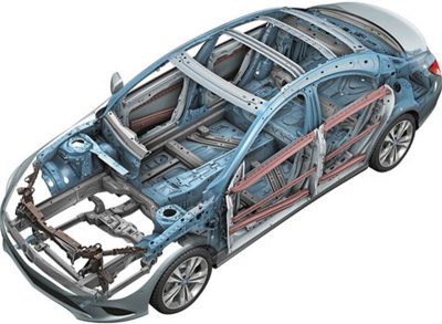
Collision energy can travel through the vehicle to other areas that may be only indirectly related to the point of impact, where it can cause secondary, or hidden, damage.
Secondary damage may be difficult to catch with a traditional visual inspection. If you miss a bent strut or control arm, the tire patch won’t hold the road properly, and your finished repair will come back from the alignment bay needing additional work.
If you want to avoid an unpleasant 5 o’clock surprise (most likely not included on the original estimate), you must search for secondary damage. Check for loose or worn ball joints, leaking or bent struts, and damage to upper strut mounts and lower control arms, tie rods, and other key components.
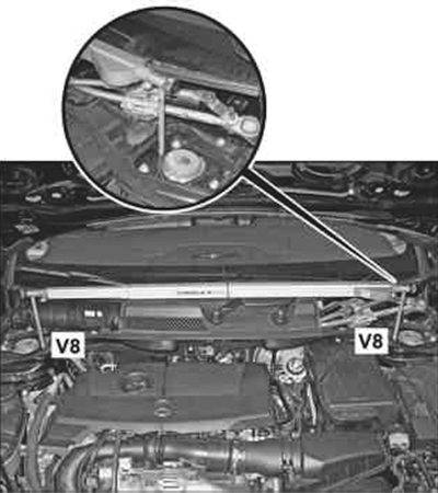
Since you are probably used to working on rear wheel drive with upper and lower control arms or wishbones, you should realize that it’s important to spend a little extra time making sure that strut tower placement and cradle alignment match OE specifications. In its Workshop Information System (WIS), Mercedes-Benz recommends taking a series of measurements to check for bent front suspension components and mounting points. The list of measurements includes, but is not limited to, the distance between the front bearings of the front axle carrier, between the rear outer mounts of the front axle carrier, between the front bearing of the front axle and the rear outer mount of the front axle carrier, and the distance between suspension strut towers.
Three angles, plus…
The big three suspension angles to check on an FWD vehicle are the same as for a RWD — caster, camber, and toe — but there are some subtle differences. We’ll go through the basics here to make it easier to see them.
Caster refers to the tilt of the steering axis when viewed from the side of the vehicle. The steering axis is a line drawn through the upper and lower steering pivot points. On traditional Mercedes-Benz vehicles, these would be the upper and lower ball joints in the control arms. With the strut system in the CLA 250, on the other hand, the upper pivot is the center of the strut’s top bearing mount and the lower pivot is the lower ball joint.
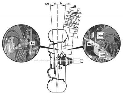
Regardless, positive caster tilts the top pivot toward the rear of the vehicle. When an imaginary line through the steering axis meets the ground at a point ahead of the center point of the tire contact area, it creates a self-centering force that helps keep the wheels pointed straight. This is responsible for pulling a vehicle back to the straight-ahead position when the driver lets go of the steering wheel while coming out of a turn.
Since the top strut mounting position on the CLA 250 is fixed, caster cannot be adjusted. Large deviations in specified caster may be due to a bent lower control arm, damaged or misaligned front axle carrier, or body damage that affects the position of the upper strut mount. After making the appropriate collision repairs, compare caster measurements on the vehicle against specifications in WIS to confirm that you have corrected the problem.
Camber
Camber is the inward or outward tilt of the top of the wheel when viewed from the front or rear of the vehicle. Measured in degrees, an inward tilt is said to be negative, and an outward tilt positive. Proper camber helps position the wheel so that it contacts the road with as even an amount of force as possible across the width of the tire as the spring compresses and rebounds. This minimizes uneven tread wear, and, more importantly, helps keep the vehicle rolling straight down the road.
A difference in camber angle that exceeds 1/2 a degree side-to-side will cause the vehicle to pull to the side with the higher camber. In other words, a vehicle will pull toward the side with the most positive camber, all other things being equal.
Possible causes of camber that does not match specifications include a bent spindle, strut, or control arm, or collision damage that has shifted an upper strut mount to one side (the first thing to measure is the distance between the strut towers). For safety reasons, NEVER try to straighten any suspension components, such as struts or control arms. If bent, they must be replaced.
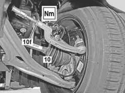
Front suspension camber is adjustable on the CLA. Check in WIS for the exact settings to achieve the desired front axle camber.
Toe in or out?
Toe is simply a comparison of the distance between the leading and trailing edges of the front or rear pair of tires. If the leading edges are closer together than the trailing edges, alignment is said to be “toed-in,†and vice versa.
Here’s where RWD and FWD differ. With RWD, as the vehicle is being powered down the road, tread drag tends to push the leading edges apart. This force is obviously not present while you are making the adjustment, so the specification will typically be toed in slightly to compensate for dynamics.
With FWD, the front wheels are pulling the vehicle forward whenever engine power is applied to them, which would tend to force the leading edges of the tires together. So, you might expect that the specification would be toed out. That doesn’t take into account coasting, however, during which mode the forces would be the same as those of a RWD vehicle. Always check WIS for the specified setting, which represents a proper compromise. Mercedes-Benz engineered in less than 1/4 of a degree of toe-in. Permissible difference in toe between the right and left sides of the front axle is ±0° 10’.
Toe settings have a major impact on tire wear. Excessive toe-in or out causes tires to scrub against the road surface even when driving straight. If toe is off by 1/8 in. (3mm), each tire on that axle will scrub the road sideways 28 feet for every mile traveled. Too much toe-in accelerates outer tread wear, while excess toe-out causes rapid wear of the inside tire edge.
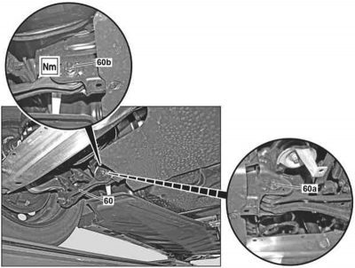
Normal wear to the tie rod ends and other steering linkage parts, in addition to collision damage, can cause toe to become out of compliance with the carefully-considered OE specifications. Any other toe setting will produce the scrubbing that eventually causes a feathered or sawtooth wear pattern on the tire.
Check for feathered or sharp edges by rubbing your hand lightly across the tread. If it feels smooth when you move your hand toward the center of the vehicle but rough when you reverse hand movement toward the outside, the cause is excessive toe-in. Sharp edges will point in the opposite direction if the problem is excessive toe-out.
Thrust Angle
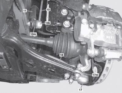
If the steering wheel is not centered while the vehicle’s wheels are moving straight, or the body appears to be moving at an angle (“dog trackingâ€), you have a thrust angle problem. The first steps in correcting this problem include ensuring that side-to-side specifications are met, and replacing damaged tie rods, control arms or other rear suspension components. You can adjust rear toe to the vehicle centerline as part of a four-wheel alignment.
Ride Height & SAI
If ride height is unequal by as little as 1/8†(3mm) side-to-side, it can negatively affect both toe and camber. Sagging, bent, or broken springs can change the vehicle ride height and therefore alter the suspension angles.
You can no longer judge whether or not ride height is in balance by how high the fender edge on each side comes up your leg. Mercedes-Benz measures the vehicle level side-to-side difference in degrees, and specifies that there can be no more than ±1.3° difference between the right and left sides at the CLA front axle.
Keeping the tire patch in the right place would be relatively easy if roads were perfectly smooth and had no turns. Since that is not the case in the real world, we have Steering Axis Inclination (SAI). This is accomplished by having the spindle attached to the axle at an angle that moves the swivel line downward from the top position, thus enlisting gravity to help keep the wheels in the straight-ahead position and to significantly reduce the steering impact of road bumps.
Strut-related Noise ComplaintUse the following procedure to check for noise before replacing a strut: Determine the side causing the problem by driving with one side of the vehicle on a rough surface. Unhook the stabilizer bar linkage prior to the test drive and check whether the noise changes. Release tension on the shock absorber/suspension strut and tighten to ready-to-drive state. If possible, swap the struts from left to right and listen for any change in the noise source. |
This angle projects the swivel line close to the centerline of the tire at ground level. The distance between the tire centerline and the swivel line at ground level is called the “Scrub Radius.†The smaller (narrower) the scrub radius, the less effort is required to turn the wheels. A smaller scrub radius also minimizes tire wear. A positive scrub radius projects the swivel line down at an angle that projects the tire centerline outboard of the swivel axis at ground level. SAI and scrub radius must be the same side-to-side on the vehicle.
Before attempting to adjust camber to fine-tune these angles, look for a bent spindle, a strut tower that is out-of-position at the top, or a misaligned front cradle.
Many other factors can negatively affect suspension angles and front wheel drive performance. For example, after a collision, Mercedes-Benz requires checking for damaged ball joints at the flange connecting the lower control arm to the steering knuckle, and where the link rod connects to the stabilizer bar.


0 Comments