With the advent of the computer, electronics have exploded in every aspect of our lives, and the automobile is no different. Mercedes-Benz is arguably the most technologically-advanced automaker in the world, but regardless of how sophisticated and productive, all M-B electronics still rely on basic wiring connections. It’s our job to keep all those connections clean, tight, and moisture-free to make everything in the electronics chain – and the vehicle — work the way it should.

Think about this for a second: The 1886 Benz Patent Motorwagen had no electrical system whatsoever! Not one wire in the whole vehicle. How far we’ve come in 128 years.
You’ve been through the drill before. Your customer comes in with an intermittent electrical problem, and, of course, when the automobile is there in front of you, it works fine. The customer can’t believe the problem has disappeared, and you both know it’ll be back, probably at an inopportune moment.
Although this could be a difficult problem to solve, logical procedures can bring it into focus, and you can fairly quickly perform some preliminary tests that will allow you to see if the customer’s complaints are indeed valid.
Always keep in mind that every electronic system that is computer-controlled still relies on basic wiring to receive a voltage supply, carry signal voltages and CAN data, operate solenoids and other outputs, and have a ground path to complete the circuit. You can check these circuits at any time, even though the problem is not acting up at that moment, to see if you have a problem connection.
Review Wiring Diagrams
After interviewing the customer to determine what systems appear to be operating improperly, one of the first steps is to review the wiring diagrams for the suspect systems. You are looking for common denominators in either wiring or connectors. Let’s look at a wiring diagram for the power windows on a 164 chassis, where we have a right rear window that is not working, either from the driver power window switch or from the right rear window switch itself.
You can use your SDS Xentry scan tool or equivalent to communicate with the front SAM, and you can look at the function of the power window switch in data. You can also bi-directionally control the power window motor using Xentry software. Let’s say neither power window switch change states while you test them in data. Let’s also say that the window did not move under actuations.
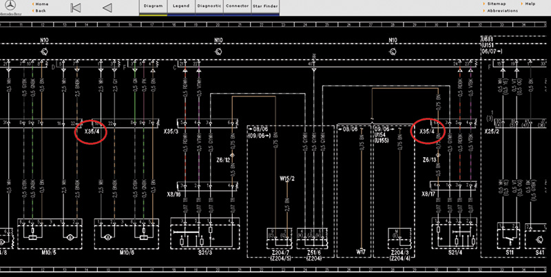
A paid subscription to www.startekinfo.com you can access factory ETMs that contain detailed wiring diagrams. What we are showing here is the common connector X35/4 that houses the wiring for both the power window motor and switch. This common connector could be the source of the problem and should be checked first.
Check Factory ETMs
By using www.startekinfo.com, you can evaluate the wiring diagram for the 164 chassis. If the data says the switch is not functioning and you cannot get the window motor to work through actuations, then either the front SAM has failed or there is a problem with the wiring. By looking at a wiring diagram, you can see that the wiring for both the switch and the motor pass through the connector in the door, which in our example is X35/4.
Since we know both the inputs from the switch and the output control travel through this connector, we can check the connections without having to pull off the door panel. This connection is normally well-insulated from moisture and corrosion, but improper repair procedures may introduce conditions that allow moisture to corrode the electrical connection, especially if a connector is mounted outside the confines of the body where water can infiltrate as it drains away.
Water, Water, Everywhere…
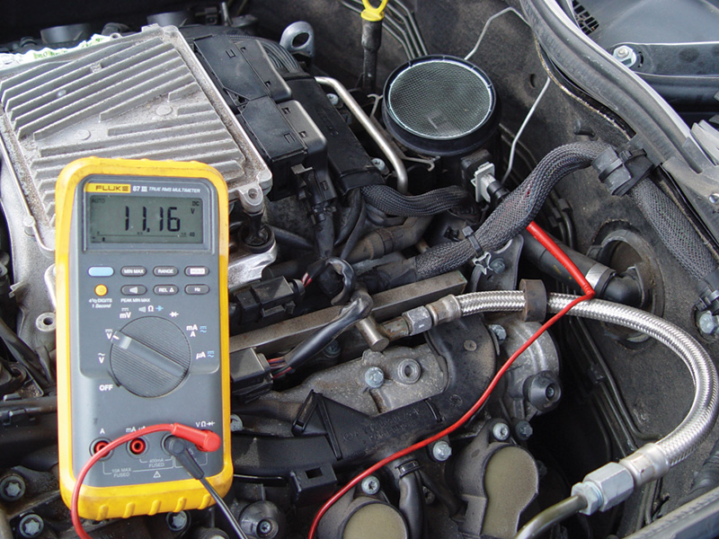
In this example, we had fuel trim codes and mild drivability issues. We checked the wiring at the MAF to verify proper function and found that the power supply voltage was 11.16V, lower than normal. This test told us to look at the power supply wiring.
Now that you know where to look, you can perform manual electrical testing. For this you will need a digital multi-meter (DMM) to measure the actual voltage, amperage, and resistance, depending on how you go about your testing. You can measure resistance with the ohmmeter function of the DMM from the source of supply voltage and the component it supplies.
This testing is possible, but can be difficult. Often the power supply is some distance away from the component it is supplying, and DMMs can’t supply anywhere near enough current to put a significant load on the circuit. For instance, a high-current item such as a fuel pump may not be getting sufficient voltage to operate, but the power supply wire may show no significant signs of high resistance in the circuit when ohms are measured with a DMM.
Voltage Drop
Measuring voltage drop is the generally-accepted way to test the integrity of a circuit. Voltage drop is often thought of as the voltage found on the ground side of an improperly functioning circuit, but can occur anywhere along the line of a circuit. This can result from wires that are corroded through from exposure to moisture or otherwise damaged, or from a connection where water has penetrated the seals and has caused oxidation.
Need Precise Measurement
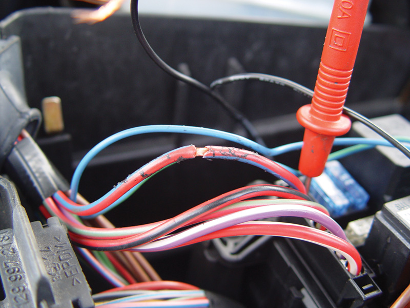
By inspecting the wiring coming out of the front SAM and powering up the MAF, you can see that someone has spliced aftermarket wiring into the original harness. This could be the cause of damage to the front SAM. So, it’s important to visually inspect the wiring if you have a problem with a control unit.
Feeling for heat in wires and connections and using a 12V test light are crude ways of uncovering resistance and inadequate supply voltage. They may work in a rudimentary fashion for simple switches directly supplying power or ground to a circuit, but you won’t be able to quantify your findings, and the test light can draw enough current to damage a delicate electronic device.
With computer-controlled outputs, reference, and signal voltages, you need more precise instruments to verify proper supply voltage, current draw, and ground potential. The DMM or a graphing multi-meter is appropriate for performing these tests, but you must know what you are looking for.
To properly test a component in an electrical system, you need to know the path it follows in the car. You can get this information from a detailed wiring diagram such as the ones found in ETMs available on www.startekinfo.com. Some aftermarket information systems also supply wiring diagrams, but they do not always include a detailed account of all the connectors and splices in the circuit.Â
The diagrams found on the Mercedes-Benz technical website provide the exact circuit path, with a detailed account of the connectors and links built into the wiring that allows you to quickly identify the location of various connectors.
This procedure can save you a lot of time when it comes to diagnosing a wiring problem. Once you have located the various connectors in the circuit where there is trouble, you can begin electrical testing. The first step in measuring voltage drop with this procedure is to know what the battery voltage is, and on vehicles with dual battery systems this is not always as straightforward as you might think. You need to measure the voltage supply at the source, and a properly charged battery will produce 12.6 volts with little to no load.
Of course, when you turn the ignition key on, the entire car will put a load on the battery — but the voltage should only drop slightly. If you are leaving the key turned on while you are testing circuits, you should install a voltage maintainer/battery charger.
Acceptable and Unacceptable Voltage Drop
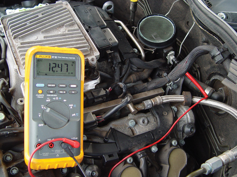
After replacing and programming the front SAM, we were able to restore battery voltage to the MAF. This corrected our drivability problem and the fuel trim codes did not return. With only a quick glance — and without testing — at the operation of the MAF we might have replaced it, with no positive results and with the problem still present. Always be sure to verify the power and ground to solenoids, relays, and even sensors before rushing to replace.
Once you have determined supply voltage, measure the voltage at the next connection. It is generally accepted that 0.1V is acceptable voltage drop across a connection. Keep in mind that every connection from the battery supply should be considered, and drops should be added up. This means the battery terminal, the terminal at the battery control unit, the connection at the front SAM, etc. If your circuit path is through five connections, you can lose up to 0.5V at the end of the circuit. This is normal and is to be expected.
If the voltage drops lower than that, you have a poor connection somewhere along the current path. Using the ETMs, go to the connections one by one and measure the voltage drop across each. This is accomplished by back-probing one side of the connector with the red test lead and the other side of the connector with the black test lead.
You can use the meter to measure the voltage difference between two connector halves. If you find a difference of 0.1V or less, it is a good connection. You can also keep the black lead attached to the battery ground terminal and use the red lead to back-probe each connection along the circuit path — expect no more than a 0.1V drop each as you get farther away from the battery. Keep in mind that if you use the negative battery terminal as the ground reference, you are measuring the drop on the basic ground wires and connections of the circuit as well. If your voltage drop adds up to be excessive, you may have a bad ground — perhaps something as simple as where a wire is bolted to the engine or the firewall.
The example we have shown here is the power supply of the MAF on a 220 chassis. The power supply comes from the front SAM to the Z7/38 leg. The engine management system was setting fuel trim codes. We suspected a bad MAF, but while testing the MAF directly we measured only 11.16V coming out of the front SAM to the MAF. We measured 12.4V coming out of the front SAM supplying the ignition coils, so replacing the MAF would have been an unnecessary expense and an embarrassment.
We determined it was a bad front SAM module. We jumped battery voltage to the MAF and the problem was temporarily solved. The voltage drop occurred in the front SAM. After inspecting the wiring harness we noticed some aftermarket wiring had been added to the MAF power supply, and this probably caused the damage to the front SAM.
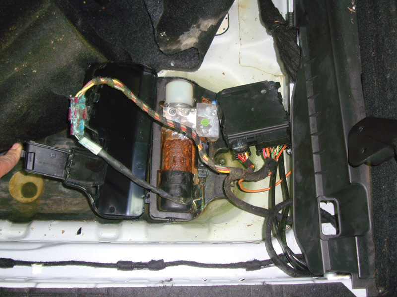
On this 164 chassis, the automatic rear hatch stopped working. A visual inspection revealed water intrusion that caused serious, unmistakable corrosion in the wiring for the hatch motor and control unit. Your Mercedes-Benz dealer can supply the factory connectors and replacement wiring with factory pin connections to repair damaged harnesses.
It is always important to check for the water intrusion that causes corrosion in both outside and inside connectors. Water can leak past worn door seals and lighting fixtures, and you should check these seals regularly along with the lower portions of the body such as the trunk, hatchback, and cabin flooring for evidence of leaks and plugged drains. Make sure convertible top and sunroof drains are clear so water does not get trapped, build up, and flow into connectors and harness splices inside the vehicle.
Likely Connection Problems
- The most common culprits in a system with weak or failing connections are:
- Water infiltration that causes corrosion.
- Broken wires from faulty procedures during repairs.
- Corrosion under bolts or screws that ground a circuit.
- Loose pin, spade, or threaded connections.
Obviously, if you find a bad or weak connection somewhere in the system, it’s the first thing to attend to before going deeper into diagnosis, or replacing components. This kind of attention to the basics will often save you the time you might have spent on high-tech troubleshooting, and make you a hero to your customer.Â


0 Comments