by Greg McConiga
Professional engine building can be one of the most tedious occupations in which a person can find himself engaged. Because each combination tends to be unique based on the application, rules, and intended use of the completed project, every measurement, every bore, and every part has to be checked on every build. One of the most critical things to know involves volumes — of intakes, of cylinder head runners, of exhaust runners, and, of course, the most critical of all, the total volume and clearance volume of the cylinders themselves, which is how we calculate the true mechanical compression ratio of an engine.
It Might Not Be What You Think It Is
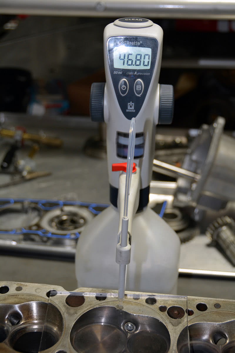
These cast iron Air Flow Research heads are rolled and feature shallow combustion chambers. A typical small block Chevy runs in the 65-75 cc range where these run 46.8 cc’s.
Have you ever heard someone say, “Oh yeah, she’s really built — I put 12.5:1 pop-ups in herâ€? But if you ask what the engine runs for compression, the guy really has no idea. It MUST be 12.5:1, right? Uh . . . not really. Compression ratio is more than just the configuration of the piston. It involves chamber volumes, valve relief notch volumes, swept volume, head gasket volume, and the volume above the ring. Your actual compression ratio could be a lot more and it could be a lot less! For example, in a recent build, a set of flat tops with valve reliefs ended up being 11:1 on a 74 cc chamber… which is actually a pretty big chamber for today’s engines. Sticking a set of “12.5:1 pop up’s in her†would have been a disaster! This engine was designed to run on pump premium because the solid roller cam used ended up reducing the dynamic compression down to just under 8:1, the upper limit for 93 octane pump premium. More on that later . . .
Two Kinds of Compression
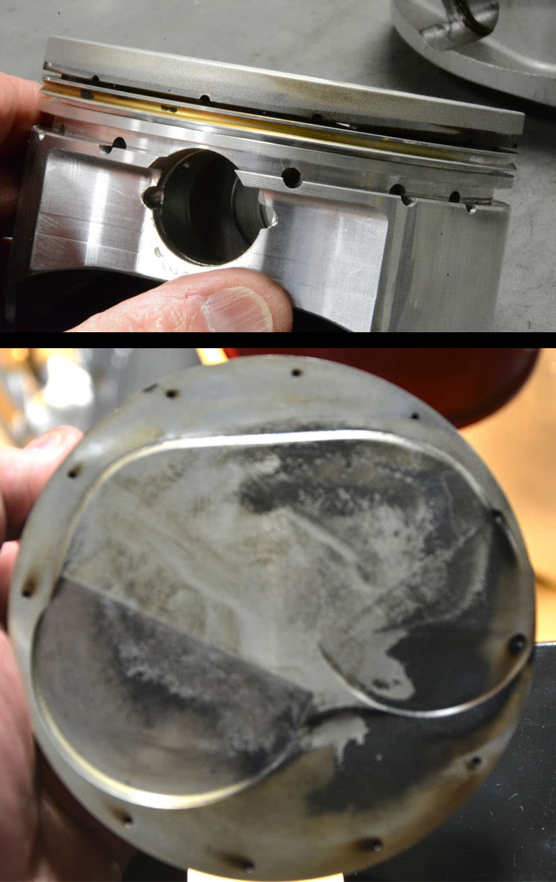
Building compression is all about sealing the cylinder. Gas porting is used to “advance†ring timing by pushing the ring out firmly against the bore earlier. Gas porting does not increase bore wear, it just seals the cylinder more quickly and efficiently. There are two ways to gas port: You can drill down from the top in behind the ring and you can drill in horizontally just above the top ring. The goal is to allow compression pressure a fast way into the backspace so that the ring seats more quickly. Vertical gas ports are more prone to carbon fouling than horizontal ones, but on drag race engines that are torn down for annual maintenance it’s not really a consideration. If you’re building duration engines, you might want to use horizontal gas ports.
First of all, we have to talk about the two kinds of compression. There is the mechanical compression ratio, the one we measure by simply dividing total volume (the cylinder volume measured when the piston is at BDC) by the clearance volume (the volume remaining after the piston is at TDC). Then there is dynamic compression ratio, which is the actual operating compression the reacting fuel and air mass sees once the intake valve goes completely closed. An engine cannot begin building compression until the cylinder seals and it’s not sealed until the inlet valve is closed, and by closed we mean on its seat. To find the seat figure, you have to actually measure the valve at the retainer. Otherwise, you won’t account for the effects of rocker ratio and pushrod geometry. Even with the valve on its seat, sealing is less than perfect since the piston rings aren’t completely sealed until cylinder pressure builds enough to hold the ring firmly on the bottom of the land and the back space is pressurized to push the ring firmly against the cylinder wall.
This, by the way, is why you see gas ported pistons. The pressure is routed into the back clearance behind the ring earlier in the compression cycle, which seals the rings earlier. To dispel an old wives’ tale, gas porting does not increase cylinder wear. The total pressure behind the ring will end up being the same; it just peaks earlier with gas ported pistons resulting in quicker and more positive ring sealing. Ring sealing timing accounts for the slight variations in the programs that calculate dynamic compression, and it’s why you often see that the predicted compression pressure is just a bit less than the actual measured compression pressure. The accuracy of the computer-generated predicted compression pressure improves dramatically as the wall finish, ring selection and piston fit improves. On race engines, it tends to be right on the number, and on street applications the predicted pressure is usually slightly higher than actual, in perfect keeping with the difference in high-quality racing parts and good quality street parts. With the right kind of equipment, you can find a direct correlation between computer-predicted pressure, cylinder leak-down, and compression pressure as recorded on the compression gauge, but to get that correlation you’ll spend at least a thousand dollars each on your cylinder leak-down tester and your compression gauge.
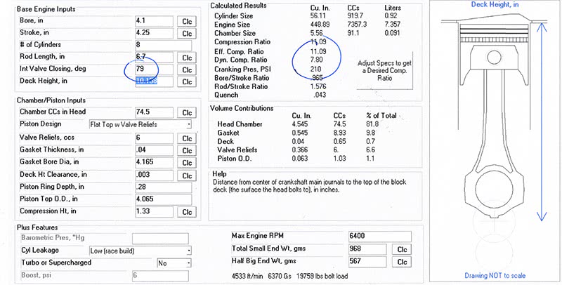
Cam Timing – Two Degrees Retarded: This compression program from Performance Trends is dead accurate IF you get the input data right. It will predict compression pressure within two or three pounds! What’s nice about it is that it lets you run different iterations and see what effect your changes have. I just finished taking compression readings on a project and the program predicted compression readings of 198 psi — and my actual readings were 195-202 across all cylinders. Static was 10.80:1 and dynamic was 7.50:1. Pretty impressive if you can get that close with a computer program! Here you see the effect of cam timing at two degrees retarded. Keep an eye on the dynamic ratio and the predicted cranking pressure as you advance the cam.
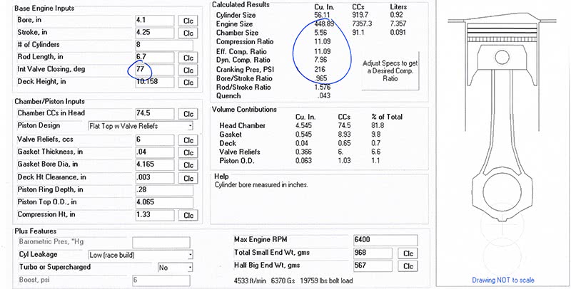
Cam Timing – As installed: By moving the cam timing just two degrees, you can see the effect on dynamic compression and the cranking pressure. The dynamic moves nearly .2 of a point and pressure goes up to 216 psi. Not a big deal you say? It may be more than you would think: At 210 psi you’re at the upper limit for premium pump gas, and at 216 you’re moving into additive and race-fuel territory. There are other factors that will move the maximum allowable compression higher or lower, but you’re in dangerous territory if you hope to run 93-94 octane pump gas.
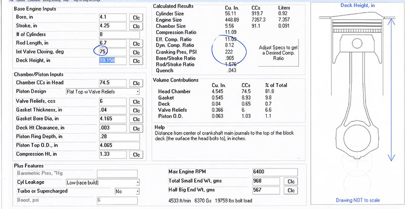
Cam Timing – Two Degrees Advanced: Okay, now you’re in the soup. Just another two degrees advanced and your dynamic is up to 8.12:1 and your compression pressure is at 222. I can tell you for a fact that an iron-head 350 Chevy 350 hp will detonate like crazy at 222 psi on pump premium, even with the timing trimmed back as far as possible while still maintaining reasonable torque. Aluminum heads, fast burn chambers, and a highly efficient cooling system can help control the detonation, but you’re walking a fine line here if you’re looking to fill up at the local gas station. Compression is good, but too much cranking pressure makes tuning a nightmare. Sometimes you will make better power with less cranking pressure and a more aggressive tune than you will with too much compression and a tune-up that covers up a poorly-thought-out build.
Despite What You Hear Too Much Isn’t Just Right
So, how much dynamic can you run? Well, it varies (doesn’t everything in a high performance application?), but in general you can run about 8:1 dynamic on the street, which will give you compression gauge readings of 190-205 pounds per square inch. Too much over that and you’ll have to start looking at racing fuel or octane boosters. I can tell you that at 225 psi on an iron-head 1970 Chevy engine you will detonate hard on 93 octane pump gas.
For racing engines, again it varies. I generally see most engines at something between 9:1 and 9.5:1 dynamic, with cranking compression pressures at 225-290 psi. There are exceptions (really?). I’ve seen restrictor plate engines over 10:1 dynamic with compression pressures over 340 psi, but you’d better know what you’re doing if you wander up into that territory!
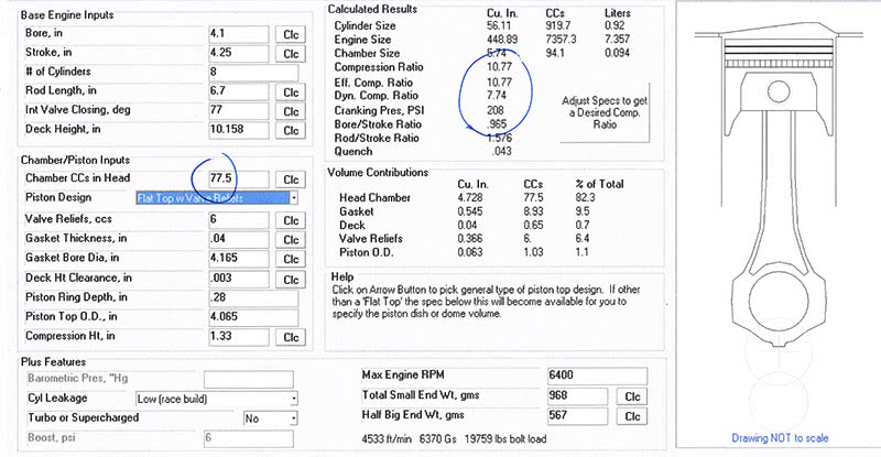
Programs like those written by Trend Performance will make your compression ratio calculations fast, accurate, and easy, and the screen shots shown will quickly explain all the variables you’ll need to consider when calculating actual compression. The program calculates dynamic compression ratio, quench, rod-to-stroke, bore-to-stroke, and cranking pressure. It’s amazingly accurate IF you get the data right! I’ve had several engines that I ran the program on and it got the cranking pressure within a couple of pounds. Take a second to look at the screen shots and the data the program asks for. Also study the screen shots showing the effect of cam timing and chamber volume on static and dynamic compression. It doesn’t take much to go from “okay†to “oh, no!†One cc is twenty drops, and six cc’s will take you from good to bad, and that six cc’s can be gained or lost anywhere in the clearance volume.
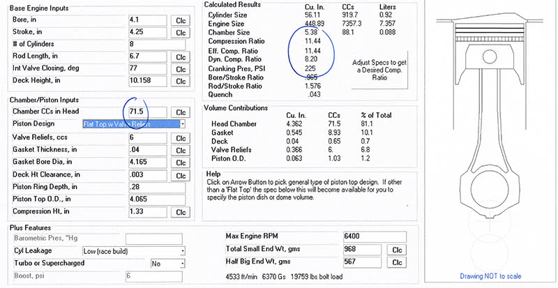
Chamber volume – 3 cc’s smaller: Now let’s look at what happens if we hold the cam timing steady and vary the chamber volume. If we reduce chamber volume by just three cc’s, the static increases by nearly .35 of a point, the dynamic rises by .24 of a point, and the pressure increases from 216 to 225 PSI. The volume we’re talking about here isn’t much — it’s only about 60 drops of water! Drip 60 drops of water in your palm and see just how little that is.
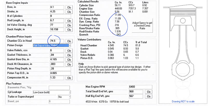
As Built – Actual Compression pressure 205#: Here are the as-built readings. Compression pressure came in a bit lower than predicted, but that’s probably because of push rod geometry, which is affecting actual valve closing timing. I’ll have to check net lift and net valve closing timing on the next angled pushrod engine I build.
Static
What is static compression and why is it important to us? At what point in the design process do we need to begin thinking about compression ratio and compression pressure? Addressing the second question first, we have to begin thinking about compression ratio and pressures right from the first — from the time pen touches paper in our design process. It is critical to engine power and it has a direct effect on engine component selection, including, but not limited to, cylinder heads and camshafts, which are the two parts most responsible for power and performance.
Compression ratio and pressures are also very application-specific. For example, if you’re running an air-limited application such as a restrictor plate or a small carb on a big-displacement engine you can and should increase the compression ratio to make up for the intake vacuum created by an oversized air pump pulling against the undersized fuel mixer system. In cases where the engine is air-limited you may run compression up to as much as 18:1. You may also see extremely high compression ratios on engines operating at extreme rpm. If you’re attempting to fill a cylinder and empty it at extreme rpm, closing the intake very, very late and initiating exhaust blow down very, very early works to your advantage.
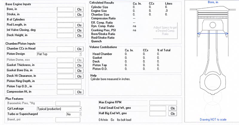
If you want to get accurate compression readings, you’ll need all the readings you find in this screen shot of the compression program. To calculate dynamic compression, you’ll need to calculate total cylinder volume at the time of intake valve closing and divide that figure by your clearance volume. You can do all this by hand — it just takes a minute. It’s changing all the variables and seeing what that does to your proposed build that takes all the time. Plus, you can make errors doing it by hand. The program is worth every penny in my opinion.
What Was That Again?

Notches, walls, dams, and domes — tons of surfaces that pressure waves can reflect off of and coalesce against. It’s amazing that we made the power we did with everything going on in this design. The “noisier†the chamber, the more attention needed for the tune-up and fuel curve. Definitely not a forgiving design.
Compression ratio is what we build and what we measure, but it’s really the expansion ratio that most concerns us. The pressure decay curve on the expansion side during the power stroke is what dictates how much power can be extracted over what rpm range. A high compression ratio engine has a much steeper pressure decay rate during the power stroke, and therefore most of the work and more work can be extracted farther ahead of BDC. This in turn means that we can pop the exhaust valve open earlier, which then extends the blow-down period. This creates a higher pressure/velocity exhaust pulse, which improves exhaust-driven cylinder fill during overlap, which in turn reduces intake charge dilution, and that results in improved volumetric efficiency. It goes without saying that increasing the compression ratio also changes the cam valve overlap, lobe separation angle, and duration design parameters.

Here’s an example of a piston used on shallow combustion chambers. If you can put a flat top in an engine, it will always produce the most consistent and uniform combustion process. Domes add complexity and one more variable you’ll have to engineer around.
You can also see that as you increase compression ratio you are also able to decrease the size of the exhaust valve and increase the size of the intake because as the blow-down period increases with earlier exhaust valve openings, you can use a smaller valve to achieve the same gas exchange efficiency. Higher pressures for longer time periods drive higher flows through smaller openings. Increasing the size of the intake valve is ALWAYS a good thing (up to the bore limits) because the differential pressure across the intake is limited to the difference between the negative pressure above the falling piston during intake (typically only 10-30 inches of water) and atmospheric pressure (14.7 psi at sea level.)
The intake side is always a bigger problem to make flow efficiently than the exhaust side because we may have 60-90 psi of pressure differential at exhaust valve opening versus a total of 16 psi difference across the intake valve. The exception to this pressure differential on the intake side occurs during overlap on a properly-designed and highly-tuned racing engine when the negative pressure created in a properly tuned exhaust system reaches as much as 120 inches of water, making total pressure differential across the inlet valve something on the order of 18-19 psi. Better, but still significantly less than the exhaust side. For any given bore diameter, you only have so much room to stuff two valves in a parallel- or stagger-valve engine (we aren’t talking hemis here; they’re a special case), so using higher compression to help increase intake valve diameters only makes sense.


0 Comments