


The 3.2 liter engine is a six-cylinder non-turbo engine. In this article, we will cover the replacement of the engine timing chain and related components on an XC90. The procedure may differ on other models.
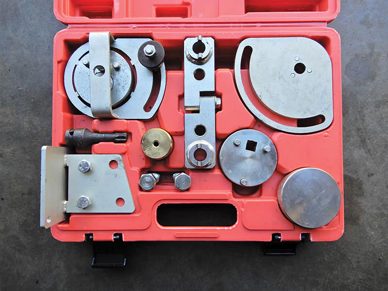
To do this job you will need some special tools: front crankshaft tool number 9997257; front camshaft tool lock number 9997261; the anvil block, two of them (they hold the camshaft gears on the timing chain side); intake side Volvo tool number 9997264; and exhaust side, number 9997263. You will need a torx T60 wrench for the center bolts for these gears, Volvo part number 9997272. The position sensors for the timing chain cover when assembling, two of them, are Volvo part numbers 9997266 and 9997267.
Set the vehicle on a hoist and drain the coolant and oil. Remove the front right tire and inner fender. Remove the plastic plug at the crankshaft and insert tool number 9997257 and turn with a ratchet until it lines up in position. The little pin on the tool will lock into place when correctly installed.
Remove the top cover over the engine and set it aside. Remove the coolant expansion tank from the vehicle. Remove the torque mount and bracket to get access to the front camshaft plug seals. Using a screwdriver, puncture the front plastic plugs and pop both out. Insert tool number 9997261 on the front of the camshafts and tighten down. This will lock the camshafts in place.
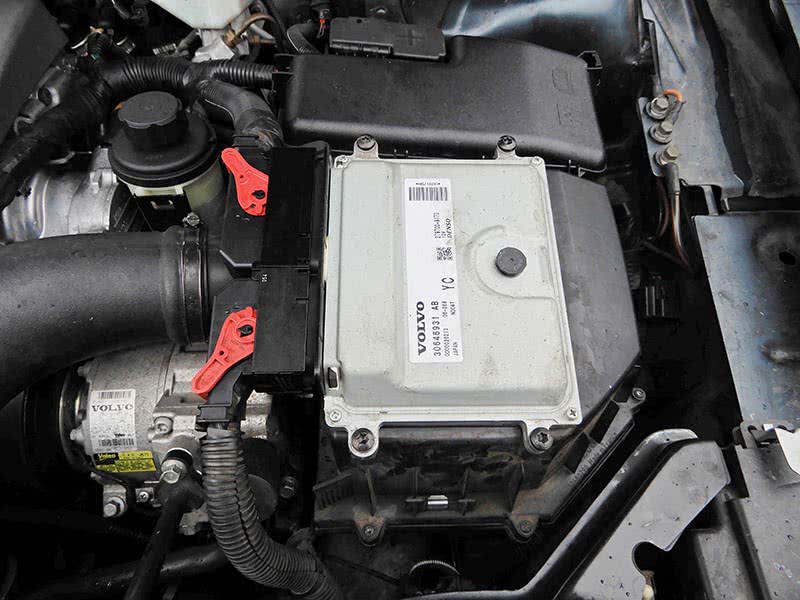
On the other side of the engine, remove the fresh air intake hose to air filter housing; two bolts hold it in place. Remove the plastic cover over the ECM on top of the air filter housing. Disconnect the two electrical connectors to the ECM. It’s a good ideal to squirt the connectors with a good penetrant/lubricant to help in removing them. Remove the cover over the fuse box and disconnect the positive cable and plug at the fuse box, tuck wires out of the way. Disconnect the hose at the air filter housing and disconnect the air mass meter electrical connector. Remove the air filter housing from the vehicle.
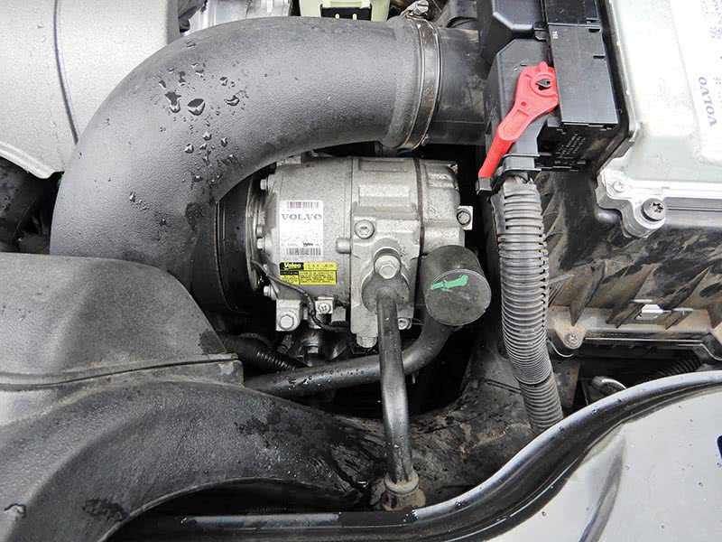
Hook up an A/C machine and recover the refrigerant from the system. Disconnect both A/C hoses, plug the hoses and compressor so moisture and debris cannot contaminate the A/C system. This will make it easier to remove the hose to the throttle housing. Once the hose to the throttle housing is removed, we can then remove the A/C compressor. Disconnect the two electrical connectors at the compressor.
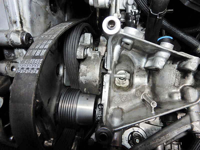
Disconnect the two bolts for the power steering reservoir and remove the bracket. Using an open end 19 mm wrench, relieve tension on the belt and insert a 3 mm pin to hold it in place. Remove the bracket from the A/C compressor to the engine.
Remove the three bolts on top of the compressor and the ones at the front of the compressor. Maneuver the A/C compressor out and set it aside. Remove the drive belt tensioner at the A/C mounting bracket.
Remove the radiator hose at the bottom of the radiator and the hose that is attached to it.
The bracket that the A/C compressor mounts to needs to be removed. There are seven bolts that hold this bracket down; remove them and the bracket.
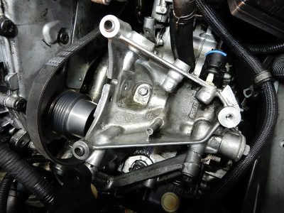
Once this bracket is out of the way, we can now start to remove the power steering pump. Extract the power steering fluid from the reservoir as much as possible. Disconnect the hoses at the bottom of the reservoir and set the reservoir aside.
Now we will want to remove the fuse box. There is a bolt under the positive cable which we already removed. Remove that bolt and the one on the other side of the fuse box. Using a tie strap, connect it to the fuse box and tie strap it out of the way. Remove the transmission gear selector cable and bracket. Remove the three bolts at the brake module and pump bracket, and pull up on the assembly so that there is room to get to the power steering pump.
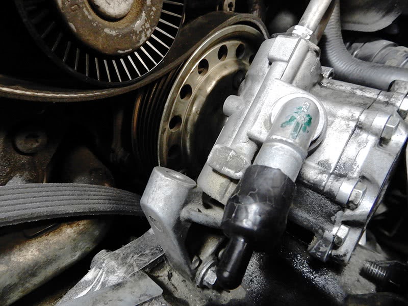
Disconnect the high pressure hose at the pump. Remove the bracket at the back of the pump. With a long stem T25 torx bit, remove the two bolts at the power steering pump pulley to water pump.
Now remove the two bolts at the bottom of the pump on both sides, and maneuver the power steering pump from the water pump and set it aside. Remove the drive belt and idler pulley.
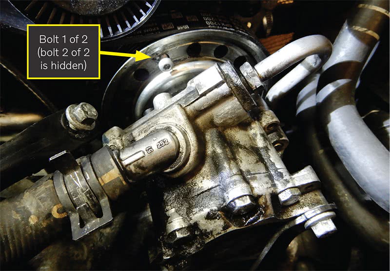
On the back side of the engine, on the exhaust side, there is a coolant pipe that is connected to the water pump. This pipe needs to be disconnected; there are two bolts above the exhaust manifold on each side that need to come out. There is also a bolt right at the water pump that needs to be removed, and then pulled loose from the water pump.
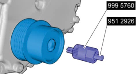
The drive belt pulley at the front of the timing chain cover will need to be removed using special tool numbers 9995760 and 9512926. Insert a screwdriver at the center of the plastic cover at the pulley and pop out the cover and discard. Use the tools to unbolt and remove the pulley.
Remove the coolant pipe at the bottom of the timing cover that inserts into the water pump housing; there are two bolts at the bottom of the cover to remove.
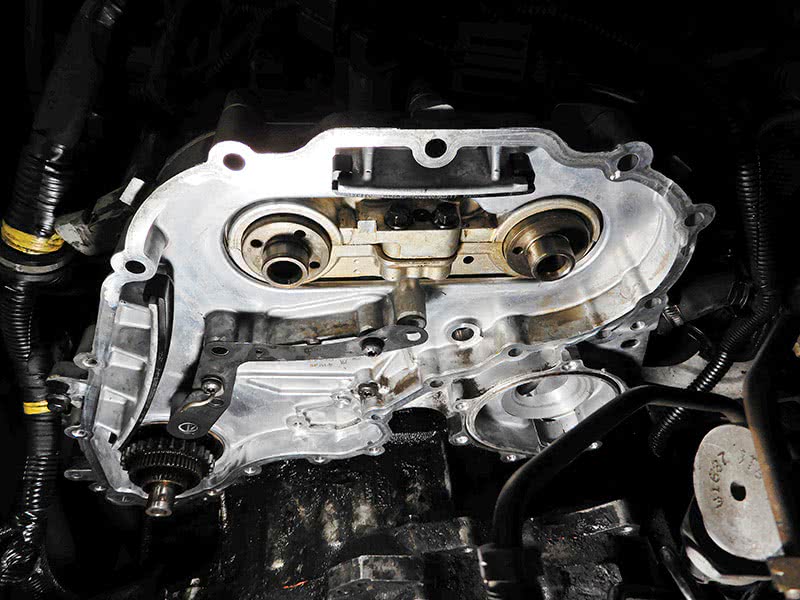
Remove the vacuum pump at the timing cover; two bolts hold it on. Now the timing cover can be disassembled. Remove the two center bolts and the 20 outside bolts, and pop the outer cover off.
On the front of the timing chain tensioner is a little tab; insert a small screwdriver and pry it open enough to push the tensioner down and lock it into place, so tension is loose at the chain. Insert the pin into the tensioner to hold it in place.
Install special tools on front of timing chain gears at camshafts, 9997264, 9997263, and 9997272 to remove the center bolts on both gears.
Remove the bolt at the tensioner guide and remove the guide. Mark the gears so you can reinstall them the same way they came off. Slide both camshaft gears off with the timing chain and remove them from the engine. Try to keep the chain on the gears and install the new chain onto the gears at the same position. This will help when installing the new chain.
This will be a good time to replace the gasket at the inner timing cover. Remove the two bolts at the tensioner guide and remove the inner cover with the water pump assembly. Clean the area really well and install a new gasket. There is also a rubber seal at the READ assembly that should be replaced at the same time, and replace the O-ring at the water pump pipe.
Back out the two 9 mm fasteners at the inner cover a couple of turns. Install the inner cover onto the engine and tighten down the two bolts to 17 Nm. Install new guide rails. Now with the new chain on the gears, install the gears and chain to the engine. Install the center bolts at the camshaft gears and leave them loose for right now.
Install the tensioning arm and new tensioner and torque down to 10 Nm. On the new tensioner, pull back the tab with a small screwdriver and pull out the pin. Let the tensioner expand and remove the small screwdriver at the tab.
Reinstall the two anvil tools at camshaft gears, 9997264 and 9997263. Use tool number 9997272 to tighten both camshaft bolts. On the exhaust side, torque to 75 Nm and then 90 degrees. On the intake side, torque to 110 Nm. Remove the tools after the center bolts at the camshaft gears are tight. Also remove tool number 9997261 at the front of the engine which is locking down the camshafts. At the front of the crankshaft, turn the engine over a couple of times just to make sure everything is lined up correctly.
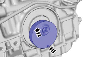
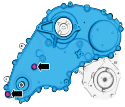
Now make sure to clean the surfaces of both the engine block and the outer timing chain cover. Install the new gasket and set the cover into place. Install three bolts in the cover but do not tighten them completely. Using special tool numbers 9997267 and 9997266, insert them in front of the cover to align the cover up into place. See image next page.
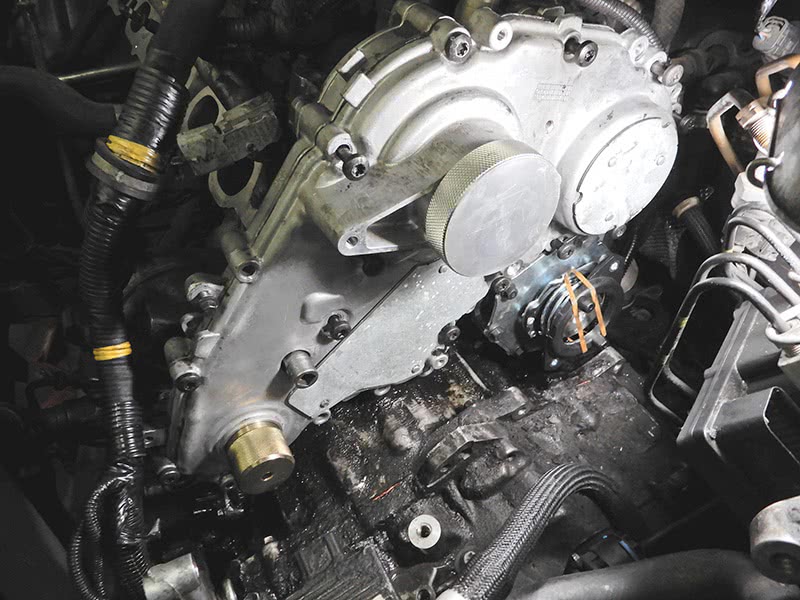
Insert the twenty 7 mm bolts and the two 8 mm bolts but don’t tighten them yet. Tighten the three center bolts at the center of the timing chain cover to 17 Nm. Now tighten the twenty bolts on the outside of the cover, in order, to 17 Nm. Remove the alignment tools from the cover.
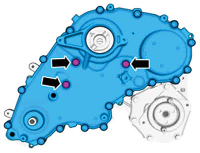
Using the 9 mm allen wrench socket, turn the two fasteners in until they touch. Install the two 8 mm bolts and tighten to 24 Nm.
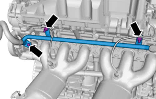
Install the pipe that inserts into the water pump and secure with the two bolts that hold it to the engine. Install the coolant pipe at the back of the engine by the exhaust manifold that connects to the water pump. There is one bolt at the pump and two bolts that secure the pipe near the exhaust manifold; torque bolts to 17 Nm.
Install the power steering pump onto the water pump coupling pulley, making sure to fit it into place properly. Install the drive belt first around the pulley before inserting the power steering pump to the water pump. There is a plastic pin that fits into the center of the power steering pump that fits into the water pump.
Once the power steering pump is correctly installed to the water pump, install the two bolts that secure the pump to the engine and tighten down. Install the bracket at the back of the pump and tighten down. Install the two screws at the power steering pump to water pump coupling pulley and tighten down. Connect the high pressure power steering hose to the pump using a new O-ring at the pressure hose.
Install the vacuum pump at the intake camshaft at the timing chain cover, lining up the vacuum pump drive to the camshaft. Two bolts hold the pump in place, tighten down. Install the idler pulley to the front timing chain cover and tighten down.
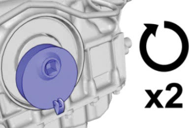
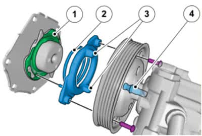
Install a new lip gasket at the intermediate shaft using tool number 9997265. Install a new coupler pulley and tighten down using tools 9995760 and 9512926. The correct torque is 60 Nm.
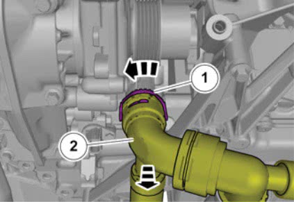
Install a new bottom radiator hose onto the pipe from the water pump. Turn the collector at the radiator hose counterclockwise to secure it to the pipe. Secure the other end of the radiator hose to the radiator and tighten the clamp.
Now set the air conditioning bracket into place on top of the transmission, and start the bolt in the center of the bracket to the transmission finger tight. Use tool number 9997262 to align the A/C bracket. Set the tool into place and start the bolts, but just finger tight at this time. Make sure that the tool is in place correctly and that the coupler pulley turns counterclockwise.
Install the bolts at the bracket except the two that have the allen wrench adjusters, and finger tighten them for now. Tighten the two bolts at the tool and then tighten the center bolt at the bracket to the transmission to 50 Nm. Insert an allen wrench at the bolt hole on top of the bracket and torque to 1 Nm, then insert the bolt and torque to 50 Nm.
Tighten the other bolts at the front of the bracket, 8 mm to 24 Nm and the 10 mm to 50 Nm. The allen bolt at the front of bracket screws in and gets torqued to 1 Nm. Intall the bolt and torque to 24 Nm. Remove the tool from the bracket.
Run the drive belt around the power steering pump pulley to the idler pulley and down to the coupler pulley. Install the belt tensioner at the bracket and leave the pin in place at this time for the tensioner.
Install the air conditioning compressor into the bracket, and route the drive belt around the pulley. Install the bolts for the compressor and tighten down. Connect the electrical connectors to the compressor.
Install the bracket from the engine to the compressor and the bracket for the power steering reservoir. Connect the hose to the reservoir to the power steering pump. Set the reservoir into the bracket and secure.
Install the three bolts at the bottom of ABS module bracket and tighten. Put the fuse box back in place and secure the two bolts that hold it down. Tighten down the positive cable and plug in the connector at the fuse box. Set the air filter box, with the ECM module on top, into place. Install the plastic pipe to the throttle housing and the air filter housing and tighten both clamps.
Connect the two A/C lines to the compressor and secure. Secure the bracket for the A/C lines near the intake manifold. Evacuate the A/C system and charge.
Install the camshaft plugs and install the torque mount at the front of the engine, right side. Set the expansion tank into place, use the proper tool to vacuum the system, and install new coolant. Install the plug at the crankshaft, the inner fender, and the wheel on the right side.
Add oil to the engine and power steering fluid to the power steering reservoir. With the vehicle still on the hoist and the cap off of the power steering reservoir, turn the steering wheel back and forth to get air out of the steering system. This could take a little while.
Start the vehicle up and check the power steering fluid; you might have to shut the engine off and turn the wheel back and forth again to let air escape from the reservoir. Start the engine back up and let it warm up. Look around just to make sure everything looks good.
Test drive the vehicle and then check again making sure fluids are full.
Replacing the timing chain on this vehicle isn’t something you do every day, but next time around will definitely be easier.


0 Comments