Last time, we discussed the basic design, failures, and what it takes to freshen up a differential. Here, we’re going to get deeply hands-on.
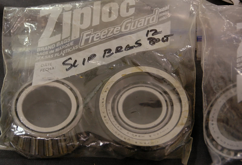
When you’ve blown a rear and the ring and pinion are destroyed, you’ll need new gears, bearings, crush sleeve, gaskets and seals, a way to measure pinion depth and a shim assortment for both depth and backlash/bearing pre-load. To ease pinion depth checking, we have several bearings that we’ve honed out to make them slip bearings. If you want to lighten the load, you can check your honed bearings against the final press-on bearing with a micrometer to verify that the inner race height is the same. In our experience, they are nearly always within a half-thousandth (.0005 in.). If in doubt of the country of origin, measure to be sure — some of the off-shore companies don’t hold dimensional tolerance worth a damn. If there’s a significant difference, just add or subtract shim thickness to compensate for the difference between your slip-fit test bearings and the final pressed version.
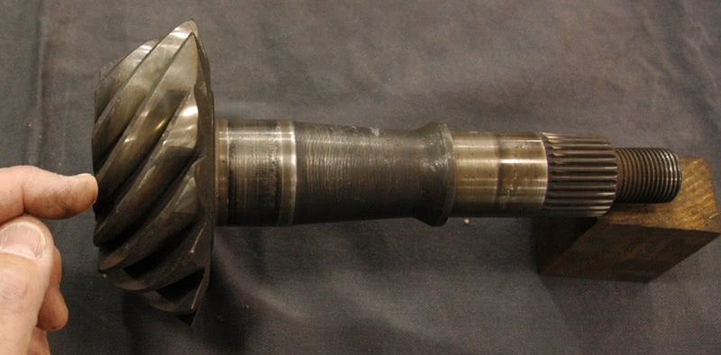
Pinion depth is the distance between the centerline of the ring gear and the nose of the pinion; the flat face of the pinion for most applications, but on a Ford nine-inch it’s measured from the small nose that fits into the rear pinion pilot or support bearing. Moving the pinion into or out of mesh changes the contact points between the gears, which moves the mesh pattern up and out of the ring gear, or down into root of the gear. Incorrect mesh is noisy and will wear the gear out in short order.
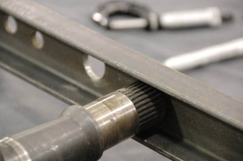
To set pinion depth, install the pinion races and fit the pinion with a depth shim under your slip bearing. We start with the factory shim. You can install the front pinion bearing and flange, or you can do what we do and use a large washer or piece of U-channel across the nose of the housing with an un-staked nut to hold the pinion tightly against its race. The quickest way to find the right shim for the pinion is by measuring the old and new pinion head thicknesses and comparing them. Look, if both are the same thickness, then the same factory shim will be correct.
The shim is used to move the pinion head into or out of mesh. Ideally, you’d like to center the pinion on the center of the ring so that both gears are engaged at their maximum thickness and therefore at the point of maximum strength. Let’s face it: Gear cutting is hard on materials and there are tons of opportunities to induce all kinds of stress risers into the parts. The only reason to move off of gear center is because of noise — in some cases moving the pinion slightly in or out of mesh by a few thousandths is enough to completely change the acoustic characteristics of the gear set. In the bad old days, they used to run the gears in what was known as a Gleason machine to determine the ideal pinion depth, which was then marked on the pinion face. We can only assume they still do something similar.
If you think it through, the housing that everything bolts into is unchanged if it’s undamaged. The bearings are precision, or should be, because there’s no way a bearing maker knows what application the bearing is going into. If bearings DID vary a significant amount, then every machine or shaft that used a bearing would have to be rebuilt or redesigned every time a bearing failed! So, you SHOULD be able to duplicate the original setup and get the same result, with the following exception: If the housing is unchanged and the bearings are all identical, then the only thing that can change is the type of cut used to make the ring gear and the thickness of the pinion head from where the bearing mounts to the top of the head. Let’s say that the new pinion head is .005 in. thinner than the old pinion head. That means that from the centerline of the pinion gear to each end of the pinion it’s .0025 in. less. So, the new pinion will need to be moved .0025 in. deeper into mesh in order to put the new pinion centerline back where the old pinion centerline was.
Then set up your pinion depth checking tool and verify that the checking height is correct. Install the pinion with the press bearings and set the preload and recheck depth and you’re done with the pinion.
Installing a new ring on the carrier requires a few extra steps. Using a large file, draw-file the back of the ring to remove any burrs or imperfections. Lightly file the carrier mounting flange, and then solvent wash both and air dry. We’ve made a set of studs for the ring gear that we use to align the bolt holes as we sit the ring down over the carrier. Using Loctite prep, we clean the holes and bolts and install and torque the bolts in a criss-cross pattern with red Loctite on the threads (Yes, even if the bolts use a lock washer. Don’t ask us why we know this is important. It involves some very expensive parts that got converted to scrap).
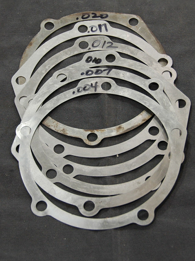
Press the carrier bearings onto the carrier, install the carrier into the housing with the factory shims, check how far off you are on backlash and move shim out of one side and into the other until backlash comes into specification. You should move about 1.5 times the backlash needed in shims. For example, if you’re trying to add an additional .004 in. backlash, move a .006 in. shim from the non-pinion side of the carrier to the pinion side. You have to move the ring gear away from the pinion centerline to increase lash and toward the pinion centerline to decrease lash. The actual amount of shim you have to move varies with ring gear size and ratio, but one and a half times will get you in the ballpark. Oh, and don’t just take out .006 in. — you have to move it from one side to the other to maintain carrier bearing preload. Remember what we said about preload: It is critical with highly-loaded assemblies. The higher the mechanical forces exerted on the assembly the higher the preload has to be to account for distortion or movement.
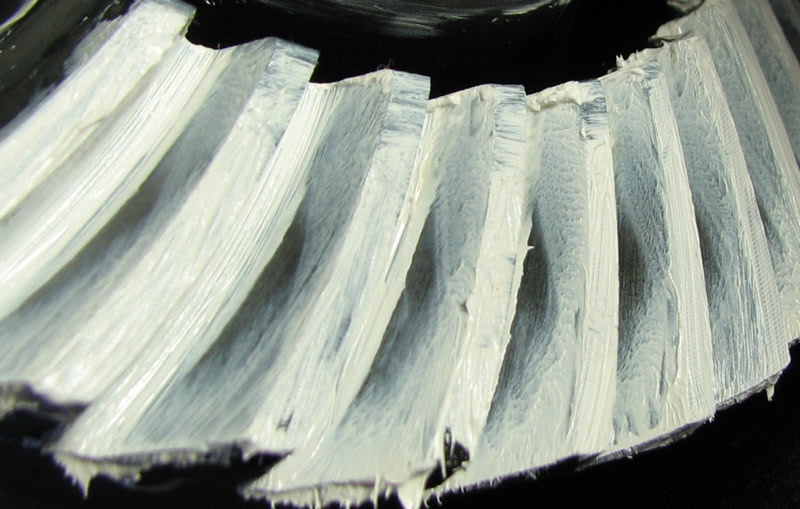
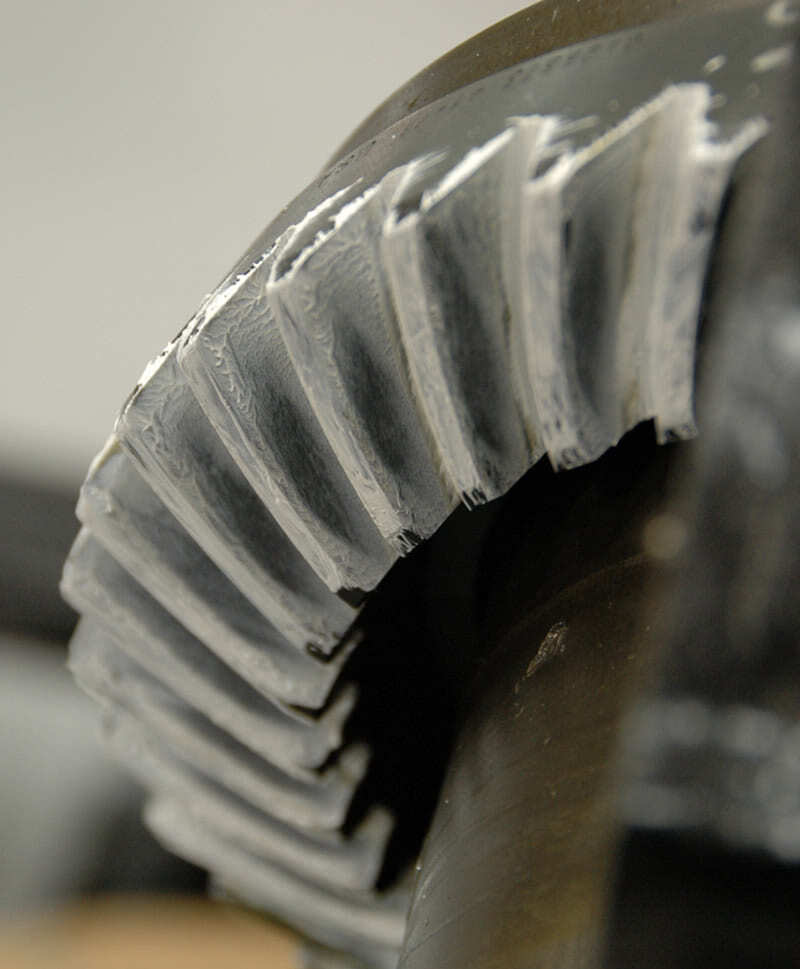
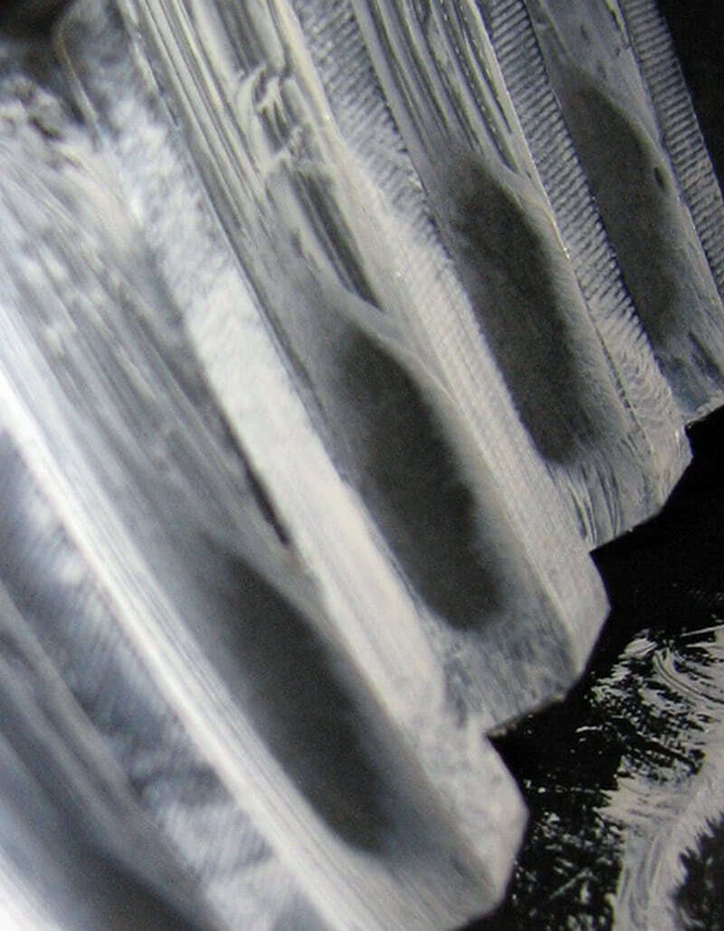
Finally, ALWAYS check your work with marking compound. Paint four or five teeth on both the drive and coast side, hold the pinion flange with channel locks, or twist a rag around the input to create load, and using a wrench on the head of the ring gear mounting bolts turn the ring against the pinion in both the drive and coast directions. The reason you load up the pinion is to apply pressure between the gears so that the gear marking compound will be squeezed out showing a clear pattern. Compare your results with the pictures supplied by the gear manufacturer and if everything looks good button it up and take it for a test drive.
Random factoids
-
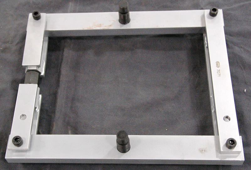
Case spreaders make life much easier when installing side bearing shims. If you have to pound the side shims and carrier races in, use brass or lead. Brass and lead will pass through the gears without damaging them.
-
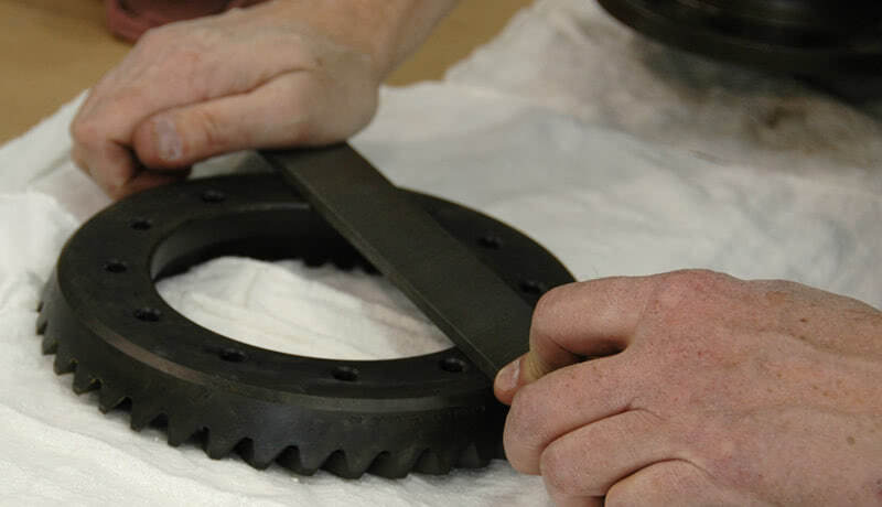
Drive pinions and ring gears come in right-hand and left-hand configurations, and a gear set comprises one right-hand gear and one left-hand gear. Place the gears on a table and you’ll see that the gear teeth cant up and down. Look for the gear tip that’s lowest — which of your hands is it on? The low gear tooth closest to your left hand or right hand determines the gear’s “handedness.†See the accompanying photos to clarify.
- You can rough in carrier bearing preload by subtracting the pinion bearing pre-load from the total assembly turning torque. I’d expect to see something in the 30-40 inch-pound range for the complete assembly with new bearings, without axles.
- Measure and record things as you take them apart. Measure the old pinion bearing inner race, the old carrier bearing inner race, the carrier and pinion shims, and distance from the cap mounting surface to the pinion head. If old bearing dimensions and new are the same, it’ll go together just like it was and you can confirm it with the pinion measurement.
- New gear sets are pre-lapped, but nearly all come with lubrication and break-in recommendations. Follow them.
- Pinion depth shims can either go under the rear pinion race, or on the pinion shaft under the rear pinion bearing. The Ford nine-inch uses a variable thickness shim under the pinion carrier assembly.
- Bearing pre-load can be set by crush sleeve or by shim. You can also use a crush sleeve elimination kit to convert a crush-sleeve application to a shim application for high-performance work.
- Backlash and carrier bearing pre-load can be set by shim or by adjusting nuts. Shims can be placed under the bearings or under the races. Some Fords use an adjusting nut with holes drilled in it to accept a spanner, and some Chryslers use a nut with a hex in the middle of it. There’s a special tool to reach down the axle tube to engage the hex on a Chrysler. Oil the adjusting nut threads and make your last adjustment on the pinion side nut to set backlash and pre-load at the same time. We try to get about two-thirds of the backlash before the final adjustment, and gather up the last third we need while we preload the bearings by tightening the pinion side nut.
- When crushing a crush sleeve, move slowly and with intent. It’ll go from no pre-load to locked-up in no time flat. You can use an impact, but it’ll take finesse. Short bursts are the safest way to go with an impact. Remember, you can damage a bearing with an impact. We’ve got a big flange-holding tool and a four-foot break-over bar in ¾ in. we like to use. If you over crush it, you’ll need a new sleeve. Go with 12-18 in. lbs. of pre-load on used bearings, and 25-30 in. lbs. with new bearings.
- Check backlash at six or seven points around the ring gear. Adjust the tightest point to specification.
- Make sure everything is clean and dry for assembly. Dirt on the shims can make the pre-load settings read correctly on assembly only to have it go away when the dirt crushes or washes out. Lose the preload, and bearings quickly fail.
- Don’t pattern check a gear until the backlash is set. Take a look at the differences between the patterns made by two cut and five cut gears. A two cut, or face-hobbed gear pattern is slightly different than a five cut, or face-milled ring gear. The patterns will look largely the same, but wider or narrower and will move across the gear face. Look at the top of the gear tooth: if it’s uniform in width from end to end it’s a two cut and if it tapers from end to end it’s a five cut. Then make sure to use the correct pattern chart because it may appear that you are too far in mesh with one cut and out of mesh on the other. Know your gear and your patterns. A pattern that’s centered between the root and top of the tooth is usually correct so long as the ends of the pattern on both the drive and coast sides resemble a round nosed bullet. We’ve also found it’s easier for us to judge the coast side of the pattern.
Â
Using Master Housing Depth Dimensions to Determine Pinion Depth
Determining pinion depth on pinions that are not marked can be done using the Master Housing Depth Dimension and a pinion depth setting tool. Refer to the drawing to see how to determine your initial settings. We’ve included as many MHD dimensions as we were able to find. Where bolt counts are mentioned, they refer to the number of bolts attaching the ring to the carrier. Ring gears are measured face-up across the teeth, outside edge of tooth to outside edge of tooth. Just do the following:
- Measure the pinion head thickness (from the top of the head to the bearing mounting surface.)
- Subtract your measurement from the Master Housing Dimension.
- The result is the pinion depth.
We’ve tried this method several times with very good results. In fact, if you have a marked ring and pinion, try measuring the head thickness and subtracting it from the MHD and see if the result is the same as the markings on the pinion for depth. So far, every one we’ve measured has been the same. Remember, your final quality check has to be done with gear marking compound.
General Motors 10 Bolt Differentials
- 7.2 inch 3.693 MHD
- 7.5 inch 3.787 MHD
- 8.2 inch by 25 spline pinion 4.175 MHD
- 8.2 inch by 27 spline pinion 4.175 MHD
- 8.2 inch by thin 55-64 Corvette 4.125 MHD
- 8.5 inch by 30 spline pinion 4.262 MHD
- 8.5 inch by 27 spline pinion 4.262 MHD
- 1955-1965 10 bolt 4.125 MHD
- 1957-1964 Olds and Pontiac 4.620 MHD
12 Bolt Differentials
- Corvette and 4WD Chevy trucks
- 3.9 ratio and higher 4.575 MHD
- 3.7 ration and lower 4.565 MHD
- 8.875 inch by 1.438 pinion diameter 4.556 MHD
- 8.875 inch by 1.625 pinion diameter 4.670 MHD
- 9.3 inch 4.620 MHD
  Chrysler
- 10 bolt 8.250 inch 4.124 MHD
- 10 bolt 8.750 inch by 1.750 pinion stem 4.350 MHD
- 12 bolt 8.750 inch by 1.875 pinion stem 4.344 MHD
- 12 bolt 9.250 inch 4.625 MHD
  Ford
- 6.625 inch 3.500 MHD
- 7.5 inch 4.040 MHD
- 8.0 inch 4.000 MHD
- 8-bolt Pinto 3.450 MHD
- 8.8 inch 4.415 MHD
- 9.0 inch 4.375 MHD
  AMCÂ
- 8 bolt 8.875 inch 4.500 MHD
  Dana
- Dana 30 3.625 MHD
- Dana 36 3.391 MHD
- Dana 44 4.312 MHD
- Dana 50 4.616 MHD
- Dana 60 5.000 MHD
- Dana 70 5.375 MHD
- Pinion Depth for Dana Rear Axles (PINION DEPTH, not Master Housing Dimension)
- Dana 27 2.094
- Dana 40 2.625
- Dana 53 2.500
- Dana 70 3.500
Â




0 Comments