

Last time we looked at some complicated dynamics and compared flats to rollers. Now for the hands-on.
This is a pair of Comp full length hydraulic roller lifters that utilize a link bar system. You can see the arrow pointing up — the link bar faces inside the valley. This lifter has about the same amount of travel as the flat hydraulic, about .150 in. total plunger travel.
Once you’ve made the move to roller lifters, your choices and options get better. Obviously, friction is reduced because you’re rolling over the lobe instead of dragging over it. Where the flat lifter is velocity-limited, the roller lifter is acceleration-limited. You can only achieve so much rate of lift before the pressure imposed by the wheel on the lobe initiates contact failures. The pressure angle is the angle formed as the roller impacts the lobe. The advantage of a roller is that you can shorten duration while maintaining high lift, but in doing so the wheel almost gets driven into the side of the lobe on the opening ramp. By necessity, the first point of contact has to be something above the centerline of the cam core, otherwise the lobe just tries to knock the wheel off of the lifter. If you look at some of the photos, you can see where the roller wheel marks the lobe. There is considerable side thrust generated and this will be seen as increased wear in the lifter bushing, often in an hourglass pattern, wide at the top and bottom and at or near specification in the center of the bore. Using a larger diameter cam core helps reduce pressure angle, as does using a roller lifter with a larger wheel. If you use a larger wheel, remember that while the lift will be unchanged, a larger wheel will increase the effective duration of the cam, opening the valve earlier and closing it later. You will need to account for this when you talk to your cam grinder.

This off-the-shelf hydraulic lifter has .140 in. of total travel. Stock adjustment procedures suggest that the plunger be depressed roughly half the total travel, or about .070 in. in this case. I don’t normally set them this deep. I normally only put them about .025 in. down in the bore and I measure it with a wire gauge between the plunger and the retaining clip.
Clean sheet
If you’re starting off with a clean-sheet engine build, your best options are to use a tall deck block; a raised cam bore centerline (to reduce pushrod length); the largest cam core you can fit with roller needle bearing cam bearings; a DLC-coated keyed tool steel roller lifter with a large wheel; bushings instead of needle bearings on the axle; and low pushrod seats, with no pushrod seat offset in the lifter to prevent side loading the lifter bore bushing either axially or longitudinally, all riding in a bronze lifter bore bushing. Now that’s a pretty tall order and it’s going to cost at least $14,000-$18,000 to get it all done. Plus heads, dry sump, rocker system, pushrods, cam drive, rods, pistons, pins, rings, bearings and crankshaft, just to name a few of the big parts. Are we having fun yet? Now that we’ve seen that side of things, it’s back to reality…
Hydraulics
If you’re going with the convenience of hydraulic lifters, you have conventional and short-travel variants available. For a pure racing application, the short-travel lifter makes the most sense. Rather than the approximately .120 in. of travel found in a standard lifter, the short travels have less than half of that.
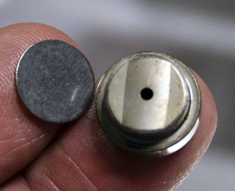
I opened up this Comp Cams hydraulic lifter. The piece on my index finger is the oil metering disc that controls oil flow up the pushrod and to the valve springs.
Over the years, there have been a number of theories about adjusting hydraulic lifter travel. The factory said to put them in the middle of travel, roughly .060 in. down or 1-½ turns down on a 3/8-24 stud. Some racers later determined that it was preferred to only put about .010 in. preload on them, about a quarter turn after zero lash, but it was discovered that the lifters would collapse at times, losing duration and lift. As it turns out, the best solution was to bury the plunger and only leave about .010 in. under the plunger before going solid. It was found that the engine oil in the column under the plunger was becoming aerated and therefore compressible, so minimizing the volume under the plunger gave the best results — as long as there was sufficient valve spring pressure and as long as no clearance opened up in the valve train during operation. If clearance developed, then the lifters pumped up, with predictable and often catastrophic results. All this led to the evolution of the short-travel racing hydraulic lifter, which addresses the issue by simply shortening the oil column below the plunger thereby making the lifter operate more consistently.
Further considerations

On the bottom of the internal plunger is the check ball that unseats with oil pressure when the lifter is on the base circle so oil can flow through the lifter body. The check ball is spring-loaded against the bottom of the plunger and when the outer body accelerates up it seals the oil inside the main body thus transmitting lobe lift to the rocker arm.
Other things to consider and look for as you install your cam and lifters:
- Make sure the lifter bores are clean and right sized, particularly with a new or unknown block.
- Make sure the bores are not galled or scored and not worn enough to cause an oil pressure leak. You’d like to see .0015-.002 in. of lifter-to-bore oil clearance.
- Always verify that you have a drilled lifter gallery if you change blocks. There are engines out there that come with both drilled and undrilled lifter oil galleries. While we’re on it, read all the literature that comes with your parts. Some manufacturers are very specific about NOT restricting gallery oil flow.
-

The stamped-steel check ball & spring cage is snapped to the inner plunger body.
If you’re running a tie-bar roller, verify that the link bar doesn’t hit the top of the lifter boss and that the link bar system doesn’t bind at full travel. You also need to visually confirm that the oil groove in the body of the lifter isn’t lifted up far enough to shut off oil flow, or up out of the lifter bore, and confirm that it doesn’t drop out of the bottom of the bore (particularly true if you are running either a large diameter or reduced base circle cam). Put the cam in place with the lifters on it one at a time from rear to front and look down the oil gallery to visually confirm that the oiling route stays open and that the oil band isn’t exposed at either the top or bottom.
- Not all lifter bore heights are the same. There are new-generation engines that have taller lifter bores and require a special tall lifter to fit the block correctly. If you have a choice, never offset the pushrod seat in the lifter. In some cases with some heads you won’t have a choice, but to the extent that you can you should try to keep the load centered in the lifter body and therefore over the lobe center, and the pushrod seat should be as deep in the body as possible to keep the bore load low and centered in the bore. If you are forced to choose between weight savings and strength, choose strength on the pushrod side of the rocker arm. The spring force multiplied by the rocker ratio is your friend at this point. On the valve side of the rocker? That’s a different matter. As Warren Johnson once famously said, “If you throw it up in the air and it comes back down, it’s too heavy.â€
There are hydraulic roller lifter cams that pull past 9,000 rpm, and there are advances going on with the pro teams that we won’t hear about for 10 years. For us mere mortals, life is a little simpler. We can pick a cam and lifters right off the shelf and go have a barrel of fun and not even lose the house or the wife over it!
 Angled trunnion tip offset pushrod seat all to get from lifter to valve tip.  Whole valve train is often designed around heads with large and moved ports. |
| On modern high performance cylinder heads, it’s difficult to get the pushrod from the lifter to the rocker seat with the larger intake ports that are being developed. This Jesel rocker has a canted trunnion axle, an offset pushrod seat, and the tip that rides on the valve stem is bent at an angle to locate over the stem center. Plus, it’s just damned pretty work. |

There’s not really too much to it. There’s the internal plunger, which houses the check ball and spring, the lower spring between the main body and the plunger that keeps the inner plunger pushed to the top of the bore, the oil metering disc, the pushrod set, and the retaining clip.
 The stamped steel spring housing has slots in it through which the oil flows, and if you look closely you’ll see the bottom of the check ball and the spring sitting against it holding it closed. |
 If you have to run an offset pushrod seat, this is the way to do it. This keyed lifter has a low seat height and the seat is down into the bore, which gives more support above and below the level of the seat. If the bore is in good shape, the wheel offset load on the lobe is minimized. Sometimes you just can’t get from lifter to rocker without offsetting the pushrod seat. |
 Here is where stock cam tunnels and stock cam bearing sizes create an issue. You can see where the base circle is undercut in the photo. Obviously, this cam will not be a stiff as something built on a bigger core and it will suffer deflection. This is not optimal for a performance application, but sometimes it’s all you have to work with. |
 Here’s what a keyed lifter bore bushing looks like. There’s no complication from link bars or pins and the seat height is very low keeping the loads centered low in the bushings. |

0 Comments