In this installment of Greg’s great exposition of high-performance rocker arms, we’ll be looking at the science and geometry involved, which you really must understand before you start building an engine.
Looking at individual parts and how they interact or operate together to cause us to increase power levels is a daily job for anyone participating in the racing or high-performance fields.
Some components are brute-force parts. These are the ones that have to be there, un-flexing, stiff and rigid, doing the job and withstanding the punishment of combustion without failing for millions of cycles. The unsung heroes — the rods and rod bolts and pushrods, the block, main caps and bolts, and the crankshaft and the gaskets that seal them all up so we don’t get waved off the track or fined for oiling it down. These parts are chosen for durability and for low failure rates. They are expensive parts (there are no good, cheap parts in racing) and we can’t go racing without them. Without them, all the parts that are more directly associated with making power have no place to call home.
Making power is a large and complex problem, and while we’ve covered it before it bears repeating: Horsepower is torque times rpm divided by 5,252, and anything that allows us to operate at higher engine speeds or generate more engine torque or reduce parasitic load puts us on the road to going faster.
Breathless?

The magic formula that goes all the way back to Scottish engineer James Watt in the late 18th century.
A major part of the horsepower chase is improving intake and exhaust conduit efficiency (and that means all the parts contained therein) while decreasing friction because friction consumes power. It’s about the right air/fuel ratio that is kept homogeneous by building in as much swirl, tumble, quench, and inertial ramming into a filling cylinder as is practical. It’s getting the cylinder sealed, or keeping it sealed, sealing it earlier in the cycle, building the engine with the right compression ratio to take advantage of the mirror image of compression or the expansion ratio because that’s where power is extracted as the piston is forced downward and it converts trapped heat and pressure into rotational power.
We have to consider our ignition system and its capability to ionize and initiate the flame kernel under high pressure and turbulent conditions.  Flame propagation and cylinder timing requirements vary cylinder to cylinder and we have to control and manage heat — by damming it, installing barriers to it, controlling it, or shedding it — using it for our purposes in the exhaust system to start the cylinder fill during overlap, or by driving a turbocharger, and keeping it from melting things down by dumping it via our cooling system.
If we are to increase rpm, we have to balance component strength with as little mass as possible and select materials that can manage the imposed loads, operate at our design speeds, and stay out of resonant destruction. The reciprocating assembly and the valve train have to be designed to do the job without premature failure while allowing us to ingest the maximum amount of air and fuel per ignition event possible given our inlet and outlet conduit flow rates because the more mass we burn the more torque we make.
The two major players in breathing are the cam and the cylinder heads. The camshaft because it determines the cylinder timing for the six critical events of compression, power, exhaust blowdown, piston driven exhaust, overlap-driven induction, and piston-driven induction. If you can’t translate the camshaft’s motion accurately — its lift and duration and cylinder event timing — you’ve just wasted a ton of time, money, and effort building a race engine that will perform well below its potential.
OHV forever
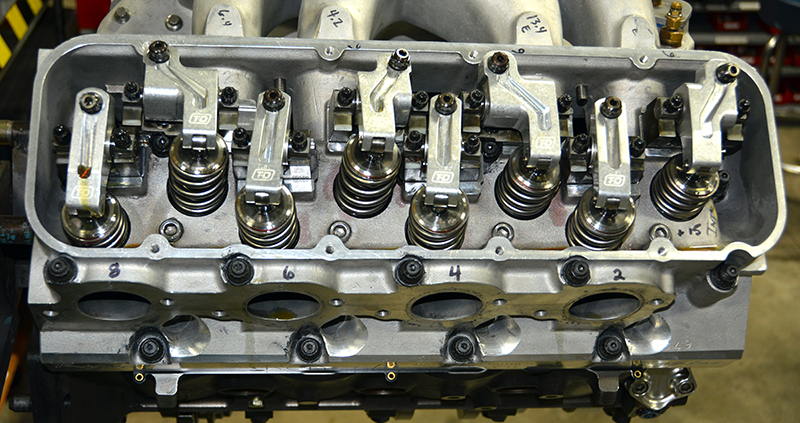
This month we continue our look at overhead valve trains with a journey into that little mystery known as the rocker arm. It’s not as simple as it seems at first glance. Look at the parts ahead of and behind the rocker itself; for example, the lifter bore. Look at the angle of the lifter bore to the cylinder bore, the angle of the rocker pivot mounting compared to the angle of the valve and pushrod; the angle of the rocker adjuster nut end and pushrod seat to the angles formed by the lifter bore and pushrod and watch the movement of the pushrod end as it moves through full lift.
Now look at the valve stem angle relative to the rocker pivot and watch how much the rocker end moves across the valve stem end. Does the pushrod move closer or farther away from the intake, head, or the bore it as it moves through full lift and back to seat? Now, imagine what will happen (visualize the changes) and how all that motion will be affected if you increase or decrease the cam lift and duration, or change the rocker ratio. Do you see it?
Do you see all the added and unwanted movements occurring that rob you of the lift and duration you hoped for when you ordered your camshaft? Look at it closely; there are more goofy angles here than you’ll find in a post-grad trigonometry textbook! Nothing is moving in the same plane or through the same arc. On most engines, there is all manner of movement tangential to the intended plane of motion and it all gets worse with longer-than-stock valves, offset rocker systems, offset lifters, specialty heads, tipped valve angles, and rolled heads.
If we measure the lift at the lifter body and multiply it by the rocker ratio, we should get the same lift number that the cam grinder got. Now, install your as-raced valve train and measure the valve lift and duration at the valve retainer. Didn’t come out the same, did it? Your final check of the valve train should always be in the “as it will be raced†condition. Checking springs are fine for rough set up, and there is a way to use the readings from checking springs to get a stiffness calculation for your valve actuation system, but the final checks before the valve covers get bolted down should always be done with what you will run with down the track.
So, when you ordered the cam did your cam guy ask you whose cylinder heads you were running and whose rocker system you were planning on using? The real lift and duration (net lift and duration) has to be measured at the valve — not the lifter — and the components between the valve and the cam all change the net lift somewhat. Any motion that isn’t linear, any component that lies at a different angle or in a plane that only partially intersects the plane of intended motion consumes cam lift and duration without translating it to the valve. Now the question becomes did the cam grinder account for that? Or, do we need to order the camshaft ground in a way to ensure that the as-advertised net lift and duration is what we end up with?
The answer is that the cam grinder does not account for lost movement between the cam and the valve and he is largely unconcerned about a few lost degrees of duration or a few thousandths lift. As engine builders, we are concerned about that and we can take steps to minimize any lost motion through either design, or careful setup and adjustment, which we will discuss.
What cam grinders and valve train engineers are concerned about is system stiffness, and there’s a good reason: The effect of not having enough stiffness is a dynamic problem and can cause valve train operation to become unstable and uncontrollable at high rpm.
Get physical

Hooke’s Law is commonly used for springs, but applies anywhere stiffness versus stress is crucial, as with rocker arms (GSU/Hyperphysics).
Okay, let’s chat about physics for a minute. Just a couple of laws, and we’ll keep it brief. Force is equal to mass times acceleration — Newton’s law, and for the sake of this discussion we will just say that mass is equal to weight (mass is actually a physical property of matter that is constant regardless of the effects of gravity; for this discussion think weight). Hooke’s law states that deformation (or strain) is proportional to the applied stress for any known or measured stiffness. Stiffness or rigidity is the extent to which an object resists deformation in response to an applied force. So, if we are considering force, deformation, and stiffness, a heavier object accelerated more rapidly will create more force, and a force applied to an object will deform the object proportionally to the force applied. A stiffer object will resist deformation; a less stiff object will deform more. See? Not so hard, is it?

These premium roller rockers for the Chrysler 273 to 360 are made of aluminum alloy with a tensile strength of 80,000 psi. That makes them stiff enough for up to 350 lbs. of valve spring pressure — plenty for just about any street application (Comp Cams).
Let’s talk about calculating system stiffness and seeing how we can minimize losses between the cam and the valve. Our good friend Billy Godbold over at Comp Cams provided us with a brief and brilliant analysis of what we are looking for. The three attributes for any component between cam and valve that affect engine performance are stiffness (resistance to deformation), mass, and durability. We want an infinitely stiff valvetrain with zero mass that lasts for eternity. I’m told this is being developed over at Comp now, but it’s a few years away from market (Billy will be getting phone calls now!). In the interim, we work on maximizing the ratio of system stiffness to effective mass. To calculate static system stiffness, you only need a checking spring and the spring you intend to run that you’ve mapped with your valve spring tester so you know how many pounds of load each makes at what length, and a dial indicator to measure the difference you see in net lift at the valve. Set the valve to zero lash so as not to induce any error and measure the difference in lift on one cylinder using all the same components other than the springs.
Then, apply this:Â System stiffness in pounds per inch = (The difference in load in pounds) divided by (The difference in lift in inches)

We’ve dealt with the physics and geometry of rocker arms here, but the next two installments of this series will get right into the hands-on details, such as oil channels (as shown here), pushrod compatibility, fasteners, etc.
For this example, let’s assume that at full lift the real spring measured 550 pounds and the checking spring measured 50 pounds and we lost .020 in. of lift. 500/.020 = 25,000 pounds per inch stiffness. According to Godbold, moving up in cam journal diameter or increasing pushrod wall thickness might gain us a couple of hundred pounds per inch while increasing pushrod diameter or going to a stiffer rocker and rocker stand might gain us considerable more. It’s a lot of work, but you have to change one component at a time and redo your calculation each time to find the parts that make the greatest changes with the least increase in mass.
While we’re on that topic, mass is a straightforward measurement with valves; we simply weight them on a grams scale. The pushrods’ effective mass is calculated by measuring the mass and dividing the result by the rocker ratio. The rocker is the trick part requiring the use of a three-point pendulum system similar to that used to weigh rod big and small ends, only with an extra point. As Billy stated, “Just remember, the mass of the rocker isn’t important unless someone is throwing it at you…†(apparently, he’s been in my shop).
In the moment
But the moment of inertia of the rocker is very important. Simply put, the moment of inertia is increased by mass that lies out and away from the central pivot. Mass near the central point has nearly no effect, but the farther away from center you extend the mass the greater the effect the mass has and the greater the inertial moment (which is why you’re starting to see some of the steel and aluminum Mohawk designs out there). Steel is very stiff, of course, and by shaving weight off of the beam the mass is reduced thereby reducing the moment of inertia. Using this newfound knowledge, you can work to increase stiffness with the least increase in mass and by doing so get more of the cam profile translated to the valve while stabilizing the valve train under dynamic conditions.


0 Comments