Volkswagen’s seven-speed automatic transmission is a technological wonder
You may recall having read in a previous issue of Volkswagen TechConnect about the six-speed automatic transmission used in a variety of Volkswagen models. But many technicians are not aware that, for several years, VW has also offered a seven-speed automatic transmission, which is technologically quite different from its six-speed brother.
To date, this seven-speed engineering wonder has only been used in the Jetta Hybrid, and, frankly, it’s unlikely that you’ll be seeing many of these hybrid vehicles in your repair bays for automatic transmission repair. However, the technology and innovation in these gearboxes is fascinating, and most technicians with any degree of curiosity will be intrigued by its inner workings. So even though you may not get involved in servicing one for years, we’re confident you’ll find that its design and function make for interesting reading.
To begin with, this seven-speed is officially designated DQ-200-7F, with the “200†referring to the torque rating of 200 Nm, the “7†referring to the number of forward speeds, and the “F†designating front wheel drive. This transmission is designated OAG. The design and function of this gearbox are especially well-suited to the operating envelope of the hybrid propulsion system, although it may find its way into other models with other powerplants in the future since the additional gear ratio can contribute to improved fuel economy and driveability along with reduced exhaust emissions.
The differences from the six-speed are many, beyond the addition of an additional forward speed. The gear ratios are different, the gear stacks are set up in a unique way, the seven-speed operates on much higher hydraulic pressure, and it also uses a dry double-clutch arrangement, as opposed to the six-speed DSG transmission, which uses a double wet multi-plate clutch setup, similar to the clutches in a conventional automatic transmission.
Modular construction is new
The Volkswagen seven-speed features a modular design, with the clutch, the transmission unit itself, and the Mechatronic electronic control system each designed as separate modules. In addition, the unit is divided into three separate control/operating systems – hydraulic, electronic, and mechanical. This transmission is air-cooled, not water-cooled, and the transmission fluid is promoted as a lifetime fill, with no routine fluid changes specified.
In effect, the seven-speed automatic transmission is essentially two manual transmissions, each with its own clutch operated interactively by the Mechatronic electronic control system. The clutches are concentric and adjacent. They are dry clutches not unlike those found in a conventional manual transmission. Engagement of the clutches is smooth and seamless, yet firm, all controlled by the Mechatronic unit.
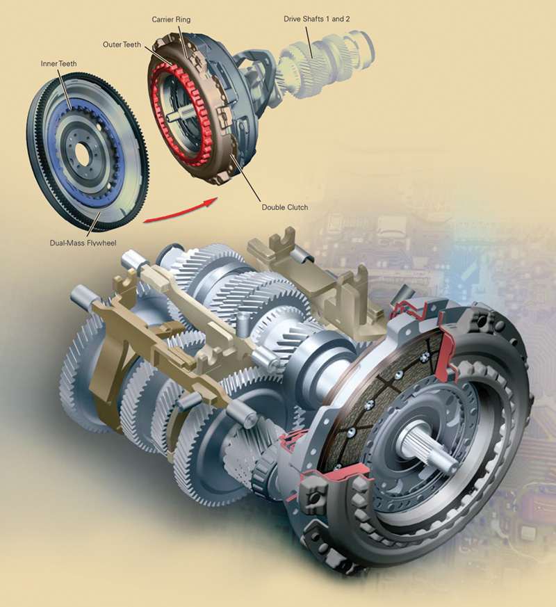
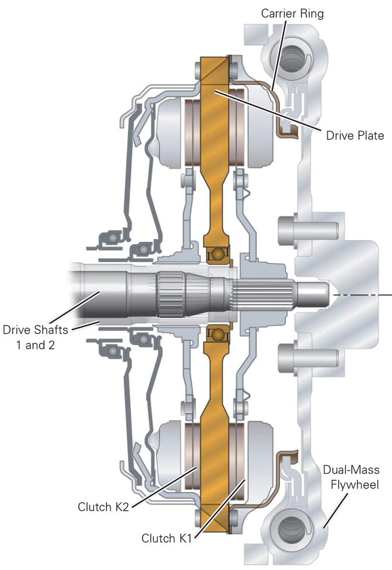
This transmission uses a dual-mass flywheel with both internal and external gear teeth. The external teeth, as you would expect, serve as a ring gear that’s engaged by the pinion of the starter motor. The internal teeth of the dual-mass flywheel are positioned to provide power to the two dry clutches by way of external gear teeth on the double-clutch carrier ring.
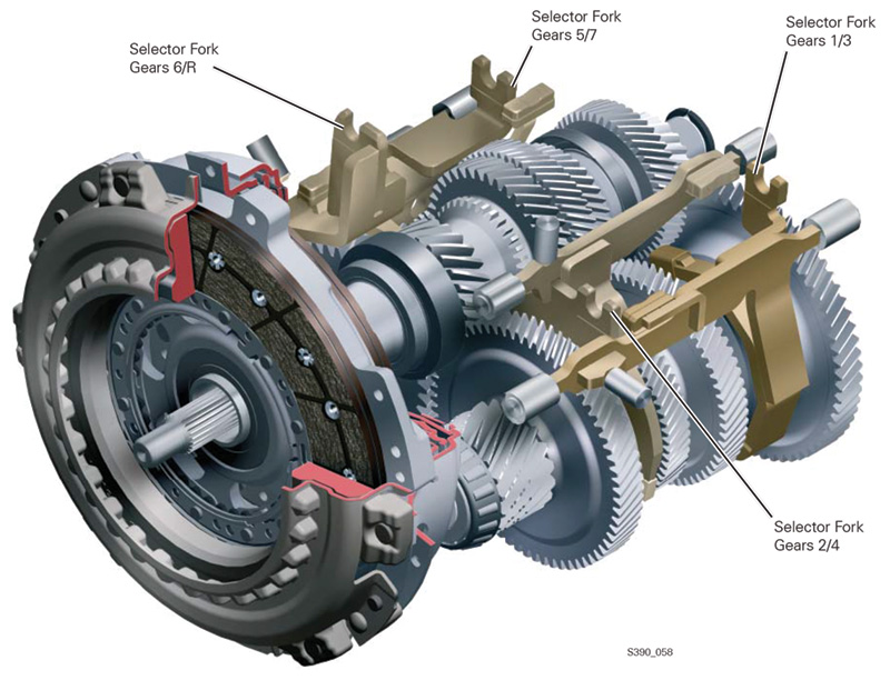
Now, envision a traditional manual transmission, in which an input shaft directly drives a cluster gear engaging various speed gears that free-wheel about a mainshaft. Gears are selected by way of synchronizer assemblies that firmly connect, one at a time, the speed gears to the mainshaft, which then directs power to the driveshaft and on to the drive wheels.
The Volkswagen seven-speed works in a surprisingly similar fashion, except that it has two “mainshafts†on opposite sides of what serves as a cluster gear, both of which have gears in constant mesh with those on the cluster.
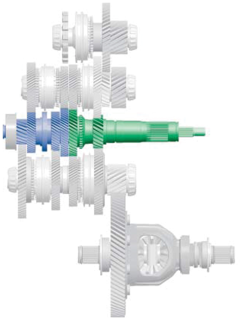
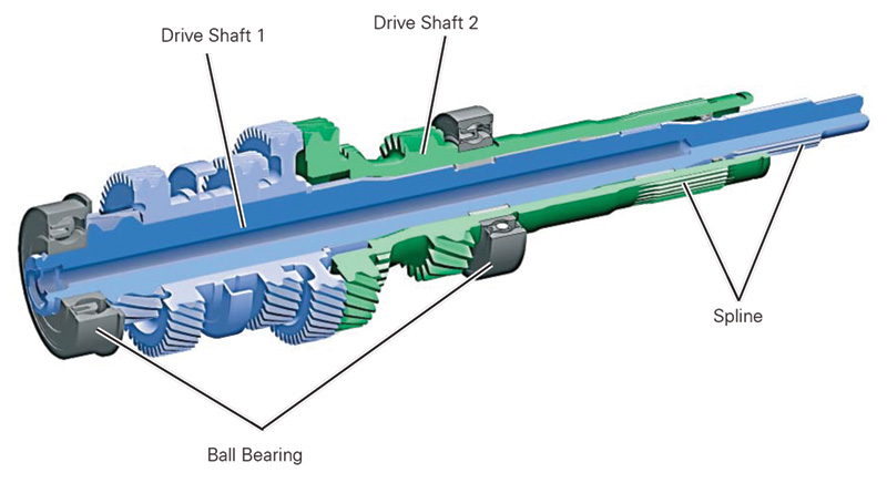
The cluster is actually two sets of gears, in-line, that ride in fixed positions on two concentric drive shafts. Each shaft is splined to one of the two clutch discs, so power may flow through one drive shaft and gears, or may flow through the other drive shaft and gears, depending on which clutch disc is engaged at any given time.
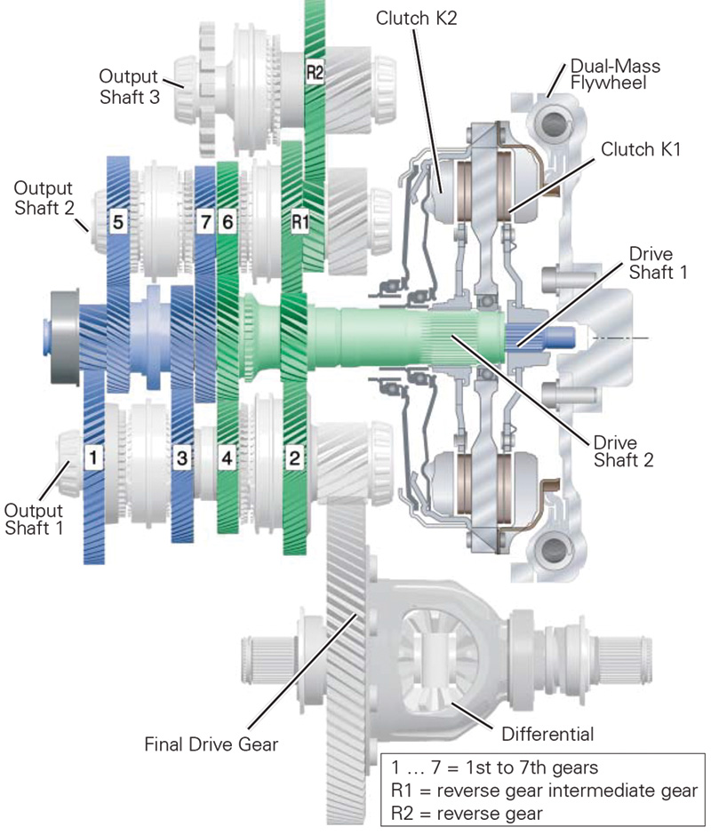
The additional gearset and shaft shown at the top provide opposite direction rotation for reverse gear, as well as a provision for a locking “park†mechanism.
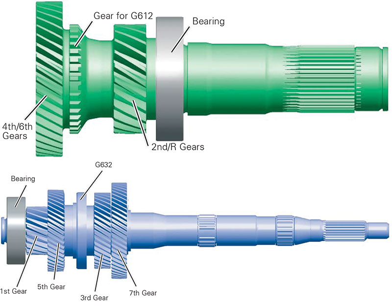
The gears on driveshaft 2, shown in green, provide power to the lower mainshaft/gearset assembly that forms a separate gear train incorporating second gear, as well as a common gear driving fourth gear on the lower gearset and sixth gear on the upper gearset, along with the clutch for this unit. The gear which drives second gear on the lower gearset also drives a compound gearset on the upper shaft which, in turn, drives the reverse gear. The gears affixed to driveshaft 1, shown in blue, power first and third gears on the lower shaft, and fifth and seventh gears on the upper shaft. This drive shaft arrangement allows for a compact drive unit that accommodates the eight (seven plus reverse) gears within this transaxle.
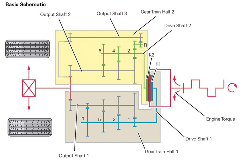
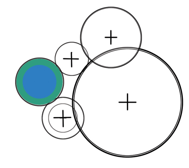
Each of the gearsets on driveshafts 1 and 2 and the reverse driveshaft are then connected to their own output shaft. So, there are actually three output shafts within the transmission assembly. All three engage the differential ring gear in different clock positions around the circumference of the ring gear.
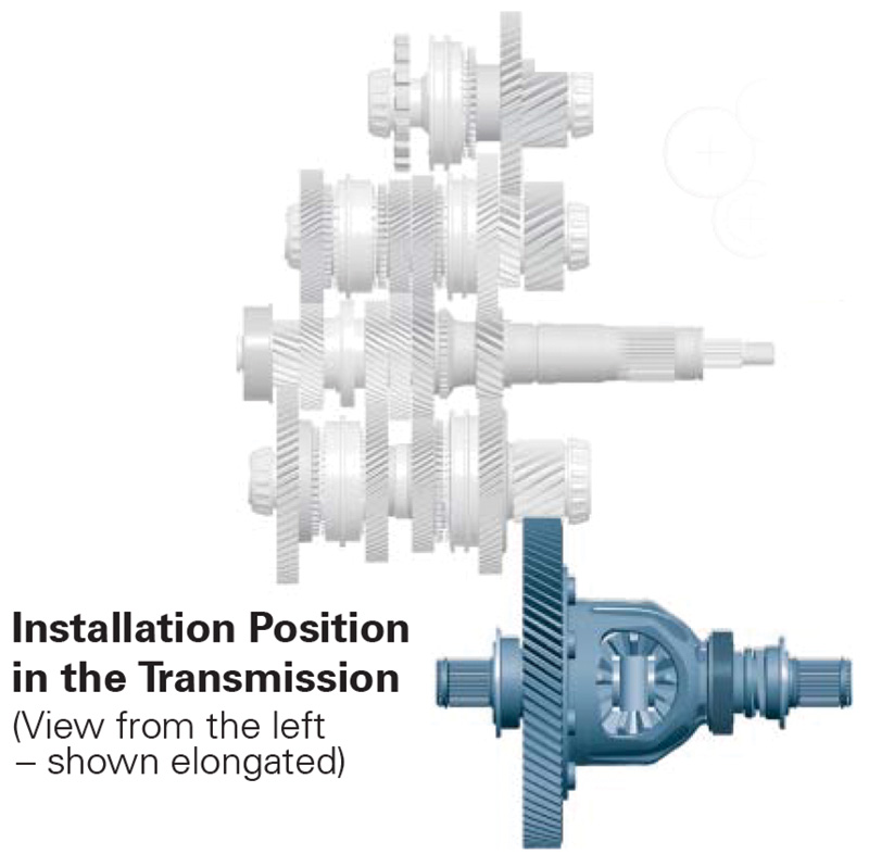
So, in effect, you have three separate pinion gears in mesh with a single differential ring gear, all engaged at the same time, but with power only being transmitted through one output shaft at a time; the other two output shafts are merely idling about the differential ring gear. This activity is analogous to the forward speed gears in a conventional manual transmission, in which first, second, third, etc., all free-wheel around the mainshaft even though they are turning at different speeds due to the gear ratios imposed by the different size drives on the cluster gear.
The genius of this transmission design is two-fold. One key feature is the use of two separate conventional dry clutches. When one is engaged, the other is not, allowing for power transmission via the appropriate gear. This also allows for the next higher or lower gear to be pre-selected before that next gear’s clutch is engaged. This allows for smoother and more immediate shifts between gears.
The other distinctive feature is that each gear cluster rides on concentric drive shafts, each driven by one of the two splined clutch assemblies. This drive shaft arrangement allows for a compact drive unit ultimately driving three output shafts, each of which has an output gear which is in constant mesh with the differential ring gear.
Each of the two “manual†transmissions uses conventional synchronizer sleeves and synchro rings as would be found in conventional manual transmissions, with important exceptions. In deference to the loads imposed on each of the various gearsets, lower gears (first, second, and third) actually use three separate synchro rings that are engaged by a common sliding synchronizer sleeve. The use of three synchro rings lightens the load on each, greatly extending synchro ring life while assuring smoother shifts under low-speed/heavy loading conditions.
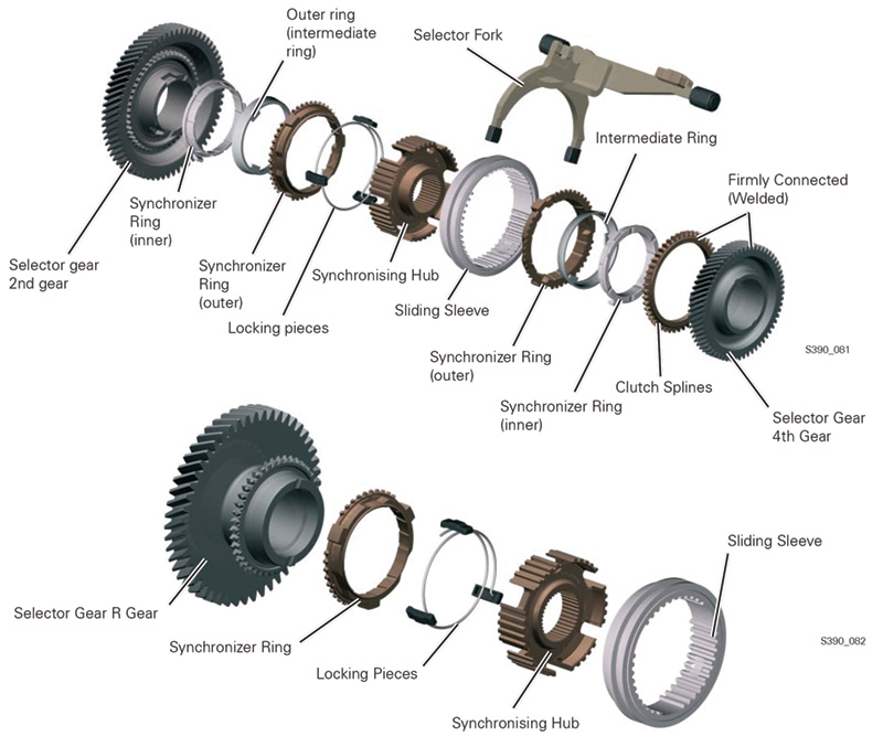
Fourth gear utilizes two synchro rings, while fifth through seventh gear, which are subject to relatively lighter loads, are fitted with a single synchro ring. Reverse gear is also synchronized to assure smooth engagement, and is fitted with one synchro ring as well. All of the synchro rings are brass with a moly coating.
Gears are selected in a conventional manual transmission manner, with selector forks moving synchronizer sleeves in opposite directions depending on the gear selected.
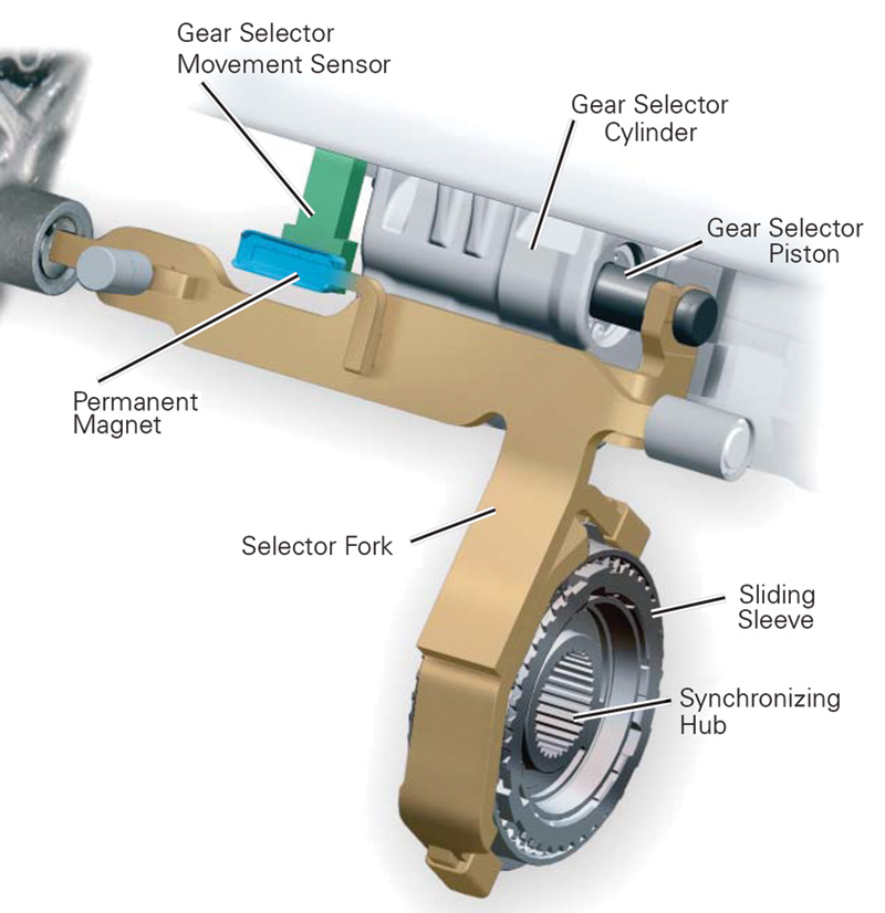
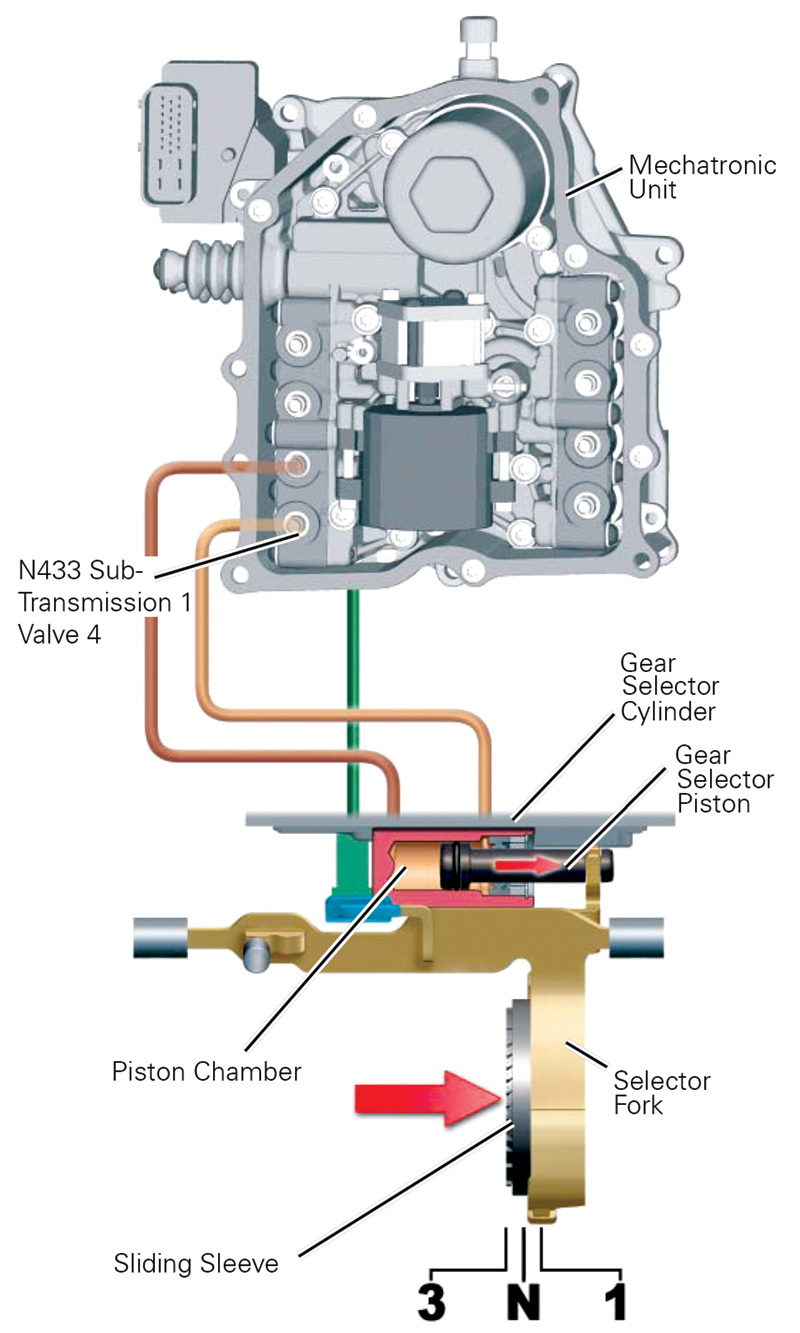
The shift forks are actuated by hydraulic pressure as directed by the Mechatronic unit. Oil pressure is applied to the gear selector piston, which in turn, moves the selector fork and sliding synchronizer sleeve. A gear selector movement sensor rides adjacent to a permanent magnet, which sends a signal to the Mechatronic unit so it knows which gear is engaged.
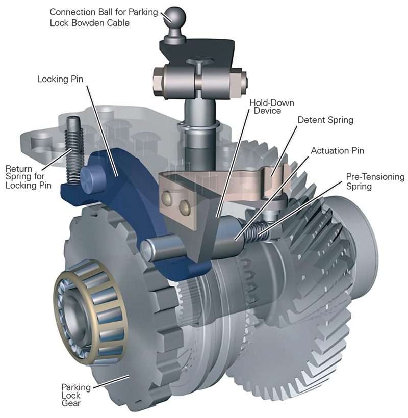
The Park function of the gearbox is performed by a fairly conventional dog ring and pawl. Engagement is purely mechanical via a Bowden cable between the gearshift lever and the parking lock tower on the transmission. This is the only function of the Bowden cable.
Coming through in the clutch
The double-clutch setup in the Volkswagen seven-speed automatic transmission, as shown on the next page, is an engineering marvel. Most technicians are familiar with dual-disc clutch setups in manual transmissions, which provide twice the contact area of single-disc set-ups, and afford extended clutch disc life along with more positive engagement during spirited driving and shifting. Of course, in such arrangements both clutch discs ride on the same transmission input shaft with a two-sided friction plate in between.
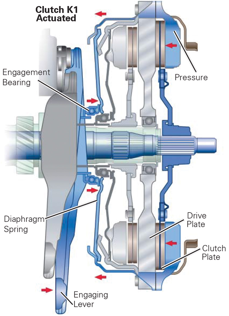
The clutch setup in the Volkswagen seven-speed automatic transmission builds on this technology, but with a twist. This double-clutch system also uses two clutch discs, but they are on opposite sides of a “drive plate,†which provides the contact surface typically provided by a flywheel in a manual transmission setup, each disc with its own pressure plate assembly.
The clutch discs each have a different size set of internal splines. You’ll recall that the input shaft that meshes with the internal clutch disc splines is actually one shaft within another, each with integral gears that essentially make for two input shafts that also function as “cluster†gears. So, in effect, you have two “cluster†gears in-line, each driven by a different clutch disc.
When the car is stationary, both clutches are disengaged. When the vehicle is in motion, one of the two clutches is engaged, with engagement and disengagement carefully coordinated with the movement of the hydraulically-operated shift forks and synchronizers. This whole process is choreographed by the Mechatronic unit, so that all of these dance partners operate in precise unity.
The brain of the system
The seven-speed transmission is controlled by the latest-generation Mechatronic unit, which is both mechanical and electronic. It incorporates 11 internal, and one external, sensors to control the eight solenoid valves for shifting the seven gears (plus reverse) and for actuating the double-clutch system.
The Mechatronic system is completely self-contained and autonomous. Besides the sensors just mentioned, it incorporates its own separate oil system and circuitry. This affords several benefits. It prevents particulate contamination that may be present in the mechanical transmission area from entering the Mechatronic unit, and contains a dedicated fluid compounded specifically for the needs of the Mechatronic unit, which differ from those of the fluid in the mechanical portion of the gearbox. And it also affords unusually good low-temperature operation since it is not subject to compromises that would be necessary if its fluid also had to serve the needs of the mechanical portion of the transmission.
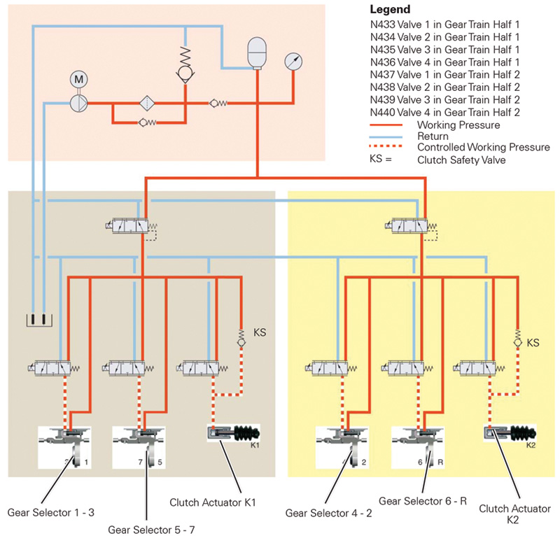
The hydraulics within the Mechatronic system consists of an electrically-driven pump, a filter, a pressure limiting valve, a pressure accumulator, and a hydraulic pressure sending unit, along with supporting circuitry. As with standard engine oil filters, there is a bypass feature that assures that the system continues to function even if the filter or related passages should become clogged.
With all components working in harmony, the seven-speed automatic transmission is able to shift smoothly and seamlessly between gears, thanks to the operation of the electronically-controlled double-clutch setup and the advanced synchronization system that makes use of multiple synchro rings in selected gears.
As noted earlier, it’s unlikely that you’ll see many seven-speed transmission-equipped vehicles come into your shop for gearbox service any time soon. And, inasmuch as they have only been used up until now in the Jetta Hybrid, the special tools and techniques for safely servicing these vehicles dictate that they only be serviced at Volkswagen dealerships with specially-trained technicians.
Since there are no externally-serviceable components here, and the fluid fill is for life, there’s no need to worry about periodic adjustments or fluid changes. Nevertheless, you have to admire the ingenuity that has gone into development of this advanced transmission, and you have to be fascinated by technology that includes dual concentric input shafts, double-acting electronic-controlled dry clutches, and gear synchronization that features multiple synchro rings.
It is indeed a technological wonder.


0 Comments