
We’ll explain the information that can be acquired with Durametricâ„¢ Diagnostic Software, when diagnosing a 2013 Porsche Cayenne that seemingly has a mind of its own when it rains or is washed.
The owner reported that another individual had “scanned†this model and couldn’t determine the fault. This became a mobile repair.
The Interrogation
Taking a bit of time and walking in the customer’s shoes can bring relevant and interesting information. It’s helpful to allow the vehicle owner to share his/her challenges with the vehicle.
The crux of the interrogation is the heavy rainfall, and most of the time, the alarm would sound with the vehicle’s lights flashing. These incidents tended to start in the evening and ended when the key fob disabled the alarm.
As the weather warmed and the Cayenne dried, the incidents seemed to disappear. The symptoms also appeared when the vehicle was being washed.
With time moving forward, the alarm didn’t sound any longer but the lights flashed on occasion. Take into account, this Cayenne is in excellent condition and exceptionally clean.
Where to Start and Requirements
An OBD II tool is not going to be helpful, and the best guess was that one of the two body control modules may have recorded the anomaly with the alarm or BCM. One thought was a door latch, hood, or rear gate defect.
The Durametric™ Diagnostic Software (v5 and v6) has been put to use with the Porsche models with great success. If you’re not familiar with it, this article will explain the information that can be acquired with the application.
What Was Tested and Behavior
With the shop tests, the alarm failed to sound/activate in this order.
Driver’s window open, hood closed, remote fob locks the Cayenne.
Opening the door from the inside, the alarm activates the Cayenne and all of the exterior lights activate with no alarm sounding. The remote fob deactivated the alarm on all occasions.
The worst case scenario is a depleted service battery or non-starting engine.
Refer to and also read these two past derFix articles:
derFix Tips and Tricks with an Audi No Start
derFix Audi A6 LIN Alarm and Parasite Diagnostics
The Initial Scan
After capturing the VIN and attaching a power supply, the Durametric application was used to access a complete scan.
The experiment also included a DLC breakout box. The DLC box was used as an “extension†to bring the Durametric USB cable to the front of the vehicle. This solution kept the equipment safe and in view during the ongoing tests with a circle check of all doors, hood, and rear gate.
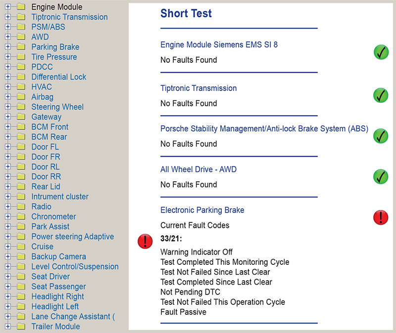
To help solve this mystery, the short test was requested after the initial identification. The identification is an aid to find manuals and schematics.
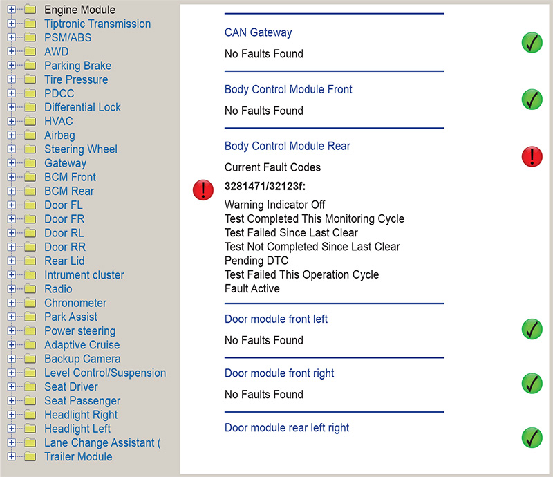
Scrolling the screen offered faults in two control modules.
Two Faults of Interest
- Electronic Parking Brake
Fault 33/21
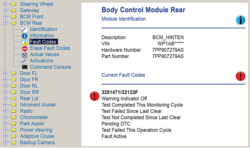
Fault Passive - Body Control Module Rear
Fault 3281471/32123F
Fault Active
Saving and clearing the recorded faults only recorded one fault:
- Body Control Module Rear
- Fault 3281471/32123F
- Fault Active
Remember, just before the initial scan, the alarm did not operate and we tested that theory again after the BCM Rear fault was deleted. That BCM Rear fault immediately reappeared.
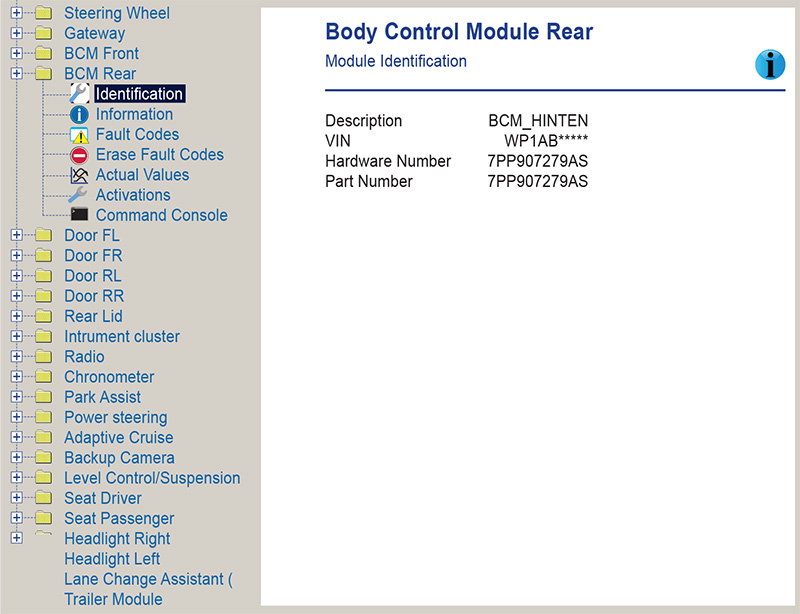
There is added Durametric information that concerns the BCM Rear and that may be critical if the BCM Rear requires a replacement.
The VIN, Hardware, and Part Number will be within the display for image Identification BCM Rear.
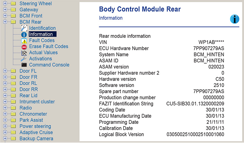
The VIN and Hardware with software version are indicated with the image named “Information BCM Rear.â€
The information provided by Durametric should help identify the BCM Rear if required. One last test identifies a repeating LIN Alarm fault.
One last point was made with the vehicle owner. Mentioned at least once was a message at the instrument panel.
The Subsequent Scan and Final Recording
The Cayenne was indicating a right rear brake light fault. The rear lighting of this model uses LEDs that operate with a duty cycle. The tail lights at near 50% and brake lamps ON at 100%. Durametric proved the correct operation, but the question arose, is the brake lamp warning attributed to the LIN alarm?
Past experience draws attention to the alarm module and a possibility of a connection with the wet weather and washing the vehicle. As mentioned, this Cayenne is exceptionally clean. Viewing below the plenum: no leaves, twigs, dead rodents, or signs of water were evident. The LIN module is mounted directly below the wiper motor and close to its center. It’s quite a distance from the bottom of the firewall. The LIN module was never submerged. Was humidity the issue?
That was day one and the customer was able to order a module at the VW/Audi dealer. The updated part shared between VW/Audi and Porsche is identical.
Day Two Testing and Cautions

Never use a test lamp with an incandescent bulb to test any LIN communications structure. Use an oscilloscope or LIN analyzer.
Many of these modules have been destroyed by unqualified “mechanics.â€
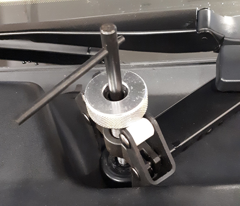
Well-made equipment is required—such as trim tools and a wiper arm puller.
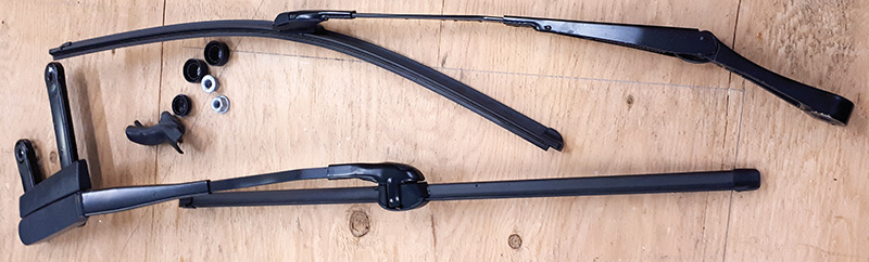
The wiper arms require removal to lift off the plenum cover.
When the arms and cover are removed, the groove at the windscreen needs to be completely cleaned of debris before reassembly.
How to Not Break Parts
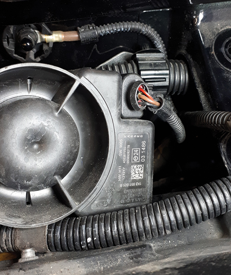
The replacement LIN alarm siren (P# 1K0-951-605-F) is located below the wiper-motor/transmission assembly, near the center of the bulkhead with the protective cover removed at the base of the windshield.
1) Gently remove wiper arm nut caps.
2) Disconnect the hood lift piston and position the hood upright with another helper or thick blanket in the windscreen. Mark the wipers with tape on the windscreen.
3) Remove the driver side wiper pivot nut with a 16 mm socket. Remove the arm with a puller (*NOTE) and place the lift piston into the original position.
4) Remove the last two retaining nuts and use the puller to lift off the arm assembly (*NOTE).
5) Starting on the passenger side, gently lift up the “tongued†plastic protector piece that sits along the windshield groove. Clean both mating surfaces before reassembly and lightly lube the tongued side of the cover.
6) Remove the five T30 bolts holding in the wiper assembly, paying attention to the correct position
of the non identical bolts.
7) Carefully unclip the larger and smaller wiring harnesses, place aside. Tilt the wiper transmission and unclip the LIN wiper motor.
| NOTE |
| Any VW, Audi, Porsche, Lambo, Bentley, Skoda, or Seat uses near identical sealed connections, and are all shared across all modern platforms. |
Push the connector towards the part to compress the seal and push back the lock to release the locking tab.
If for any reason the connector shell is damaged, the part number is visible for a replacement.
8) Two 6×1.0 mm nuts are exposed to remove the siren bracket.
9) Tilt the siren and unclip the connector.
10) Assemble in reverse order and clean all the mating splines at the wiper arms.
| *NOTE |
| Add slight pressure with the wiper arm tool and gently tap with a hammer while adding slight pressure. |
The preference is to attempt to measure the difference(s) and prove the defective LIN messages from the LIN alarm at this stage.
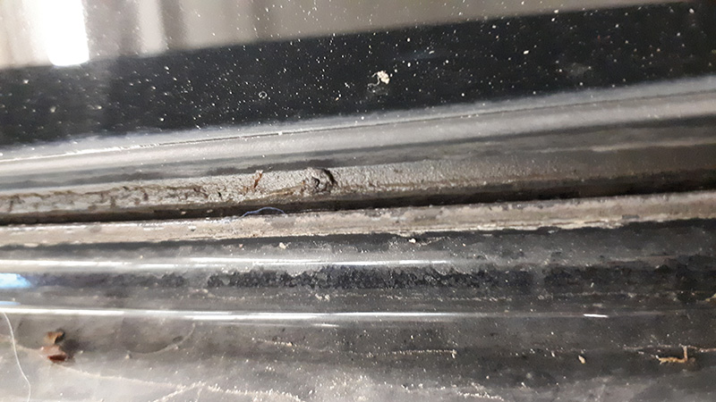
Use an anti-seize compound on the wiper pivots/splines and slightly lubricate the plenum cover groove upon reassembly. Make absolutely sure the grove is perfectly clean to accept the cover for a close and proper fit.
The LIN Message
At the time of final testing, the original LIN alarm appears to operate with no sound. The LIN message appears normal with one test and the message also lengthens during activation with the new component in place. It is very loud when activated, the anti-theft alarm set when opening a door. It only chirps once when set with no intrusion and active.
With the new LIN alarm module installed, the original fault was deleted and didn’t return. Multiple activations offered no faults.
What Did Happen to the Original LIN Alarm?
It was decided to cut the LIN alarm open and inspect the entire device.
A razor knife cut along the edges offered an interesting clue as to what happened inside the module. View the images with a magnifier.
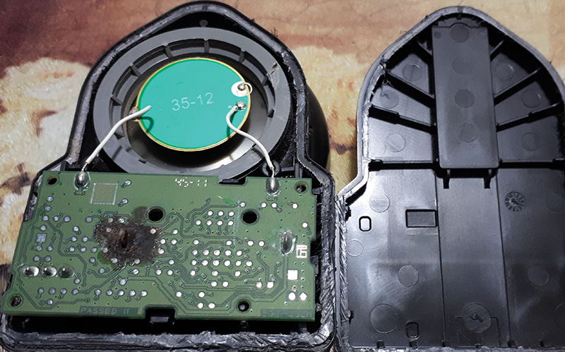
A close inspection of the LIN alarm does not indicate a water leak, while the piezo speaker is sealed with no oxidization. It seems humidity is the cause of alarm activity. The powdered substance appears to not originate from the battery but from the burning IC’s circuit board and melted solder.
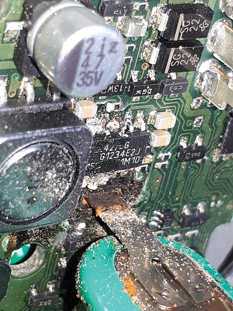
Call it the “micro big bang theory.†The battery leg may have arced.
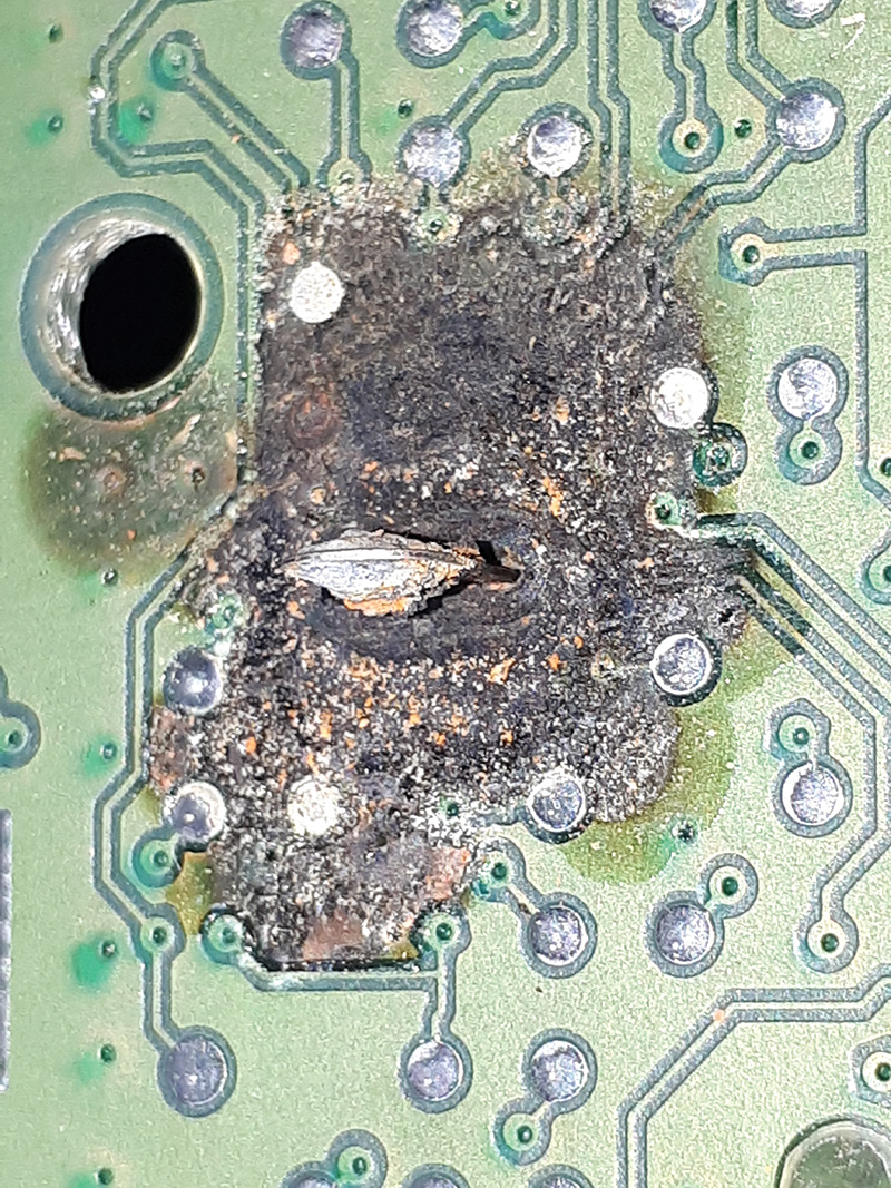
A battery solder point melted, but a close inspection indicates that one of the ICs also failed and melted. That major failure melted/arced one of the battery solder points. The combination destroyed the IC board and surrounding circuitry and traces. Refer it to a cascading failure.
The battery was de-soldered and wiped of all debris, indicating no leakage.

Schematics and Data Collection
A correct wiring schematic indicates three connections at the LIN Alarm.
- B+ (A3 ~ Terminal 30)
- B- (A2 ~ Terminal 31)
- LIN (A1 ~ Black)
A voltage drop test between A3 and A2 with the LoadProâ„¢ proved intact and correct. There were no power source issues with the LIN alarm module.
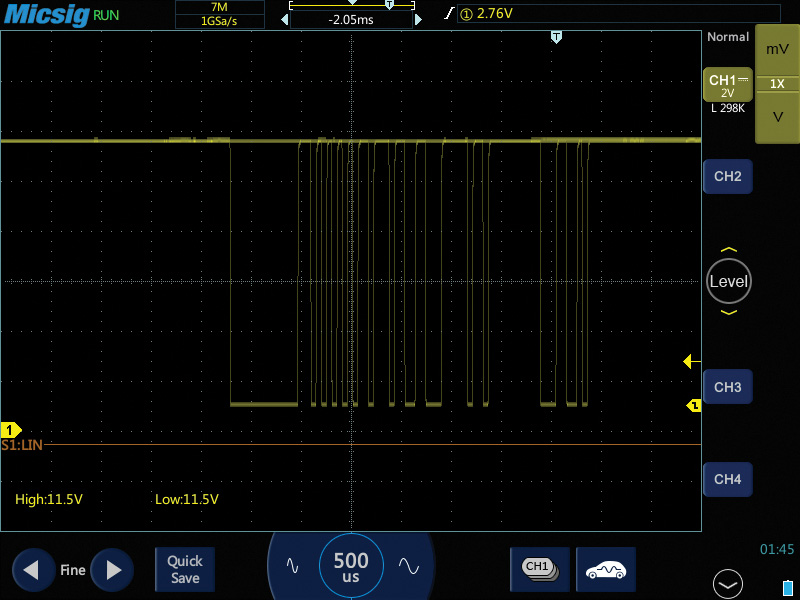
The black LIN connection was monitored with both the defective and new LIN alarm module. Comparatively, the messages with the original module appeared corrupted and highly extended.
Additional oscilloscope images, correct and incorrect schematics are available here: bit.ly/ExtraImg. They are:
- Seven oscilloscope images were captured with the LIN alarm messages within a few seconds of each other despite the alarm not operating correctly.
- Four schematics showing connections.
Earlier Faults and Conversation
One earlier fault did delete after the first scan was completed. The fault for the (EPB) Electronic Parking Brake (33/21 Passive) never returned. The EPB was exercised multiple times and operated as intended.
The conversation about the instrument cluster warning for a right rear brake light never materialized after repeated testing. It would appear that corrupted LIN messages were shared within the network and triggered those faults.
What Was Learned
Repair the major and primary issue before assuming multiple problems may be connected in this incident. Access the correct and verified repair information with matching schematics that fits the tested model.
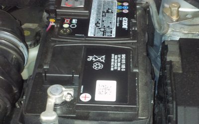
The Internal Battery
The NiMH battery was tested as normal and actually accepted a charge. The battery drove up some 5 volt hobby motors, was recharged, and held a charge. This rechargeable battery will be put to future use to drive
up some 5 volt devices.
| Tools Used |
|---|
| Durametricâ„¢ Diagnostic Software 6 with multiplexer |
| DLC breakout box |
| 90 amp floating power supply |
| LoadProâ„¢ |
| Oscilloscope |
| Various workshop manuals and schematics |
| Wiper arm removing tools |
| Assorted trim tools |
| Screen capturing software, camera, pen, and paper |
By Augie Ferron


0 Comments