The increased popularity of diesel-powered BMWs brings concerns about carbon buildup in higher-mileage engines
For the 2009 model year, for the first time in over two decades, BMW began selling vehicles equipped with diesel engines. The E90 and E70 both were available with the M57D30T2 (US) engine. This is a turbocharged common rail injection 3.0-liter diesel that meets the EPA tier 2 Bin 5 requirements. In order to meet these new “Clean Diesel†standards, some new technologies are fitted to these vehicles. This emissions reducing equipment is placed both before and after the combustion chamber. In this article, we will be looking at the technology before the combustion chamber in the air management system, and the problems it is creating.
Exhaust Gas Recirculation (EGR)
The recycling of exhaust gases is one of the methods used to reduce NOx in a diesel engine. By introducing exhaust gas into the intake stream, the amount of oxygen in the combustion chamber is reduced, which results in lower combustion chamber temperatures.
BMW gasoline engines currently do not use a more conventional “external†EGR system. EGR on BMW gasoline engines is considered an “internal†system which is carried out via the variable camshaft control system (VANOS). The VANOS system modifies the camshaft timing to achieve a precise amount of valve overlap. The valve overlap allows a certain amount of EGR to occur, thus lowering NOx significantly. Mostly, gasoline engines respond to an EGR flow rate of about 5 to 15%.
BMW gasoline engines are able to benefit from the “internal†method of EGR due to engine design and engine management strategies. In the case of diesel engines, which run in a constantly lean mode, the NOx content in the exhaust gas is much higher. Therefore, the “internal EGR†method is not able to sufficiently lower NOx to acceptable levels.
So, BMW diesel engines employ an external EGR system to meet these needs. Diesel engines benefit from EGR rates as high as 50% under certain operating conditions. Unlike gasoline engines, diesels can introduce EGR at idle. This is due to the fact that the diesel has a mostly open throttle at idle. This helps reduce NOx at idle which is when a diesel is most lean. The recirculated exhaust gas, which is mixed with the fresh air and acts as an inert gas, serves to achieve the following:
- A lower oxygen and nitrogen concentration in the cylinder,
- A reduction in the maximum combustion temperature of up to 500°C. This effect is increased still further if the recirculated exhaust gases are cooled.
The EGR valve is located in the throttle housing. Exhaust gas is ducted from the exhaust manifold to the throttle housing. There is a connection at the forward end of the manifold for this purpose. Connected here is the EGR valve, which controls the volume of recirculated exhaust gas. The EGR systems differ between the E70 and the E90. Both vehicles use the “high-pressure EGR,†but the E70 uses an additional “low-pressure EGR†system. The low pressure EGR system is required in the E70 due to its additional weight and higher operational loads (i.e. towing etc.).
Swirl Flaps
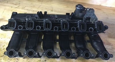
The M57 engine uses a four valve combustion chamber design much like its gasoline counterpart. However, the arrangements of the intake ports in the cylinder head are radically different. Each of the two intake valves has a separate port. One is called the tangential port and is located in the same conventional position as other intakes, on the side of the head. The other port is called the swirl port. The swirl port comes straight down through the valve cover. As a result of these two ports and their locations, the intake manifold has a very unique design.
The purpose of this air management configuration is to allow control over how air is delivered to the combustion chamber during the intake stroke. If incoming air is directed to only one valve within a four valve configuration, swirl is generated. This swirl increases the turbulent kinetic energy of the air present in the cylinder during both the intake stroke and the compression stroke. This method of air control works in conjunction with the piston geometry to ensure a more complete mixture formation.
By controlling “swirl†within the combustion chamber, significant reductions in NOx and particulate emissions are possible. This design is not exclusive to the M57 diesel engine. In fact, this takes place on every engine BMW currently manufactures for use in the automobile. With the gasoline engines, turbulent kinetic energy is increased by use of Valvetronic. This feature is known as “phasing.â€
In order to control the delivery of air to only one port on the M57, the tangential port has what is called a “swirl flap†installed in the runner of the intake manifold. The swirl flaps are controlled electrically. This method of actuation provides a means of position feedback with the DDE system to comply with OBD requirements. An additional benefit of this method of control is a more precise positioning of the swirl flaps as needed. The flaps are map controlled using engine speed, engine load, and coolant temperature inputs.
Swirl flaps ensure better swirl of the incoming air during the intake and compression cycles. The adjustable swirl flaps, located in the tangential channels of the intake system, are opened and closed according to the operating status of the engine. On the M57TU engine, the swirl flaps are closed at low RPM and load conditions. To increase the swirl effect, swirl flaps are designed to close tightly on the M57TU engines. With increasing engine speed, the DDE opens the flaps to facilitate charging through the tangential ports. The position is based on the driver’s load choice, engine speed, and the coolant temperature. The swirl flaps are varied by a linkage that is operated by a DC motor.
Effects of Swirl Flap Malfunctions
If the swirl flaps stick in the open position, deterioration in exhaust gas characteristics in lower speed ranges will develop. Otherwise there is no effect. If the swirl flaps stick in the closed position power loss of approximately 10% can develop at higher engine speeds.
Carbon Buildup
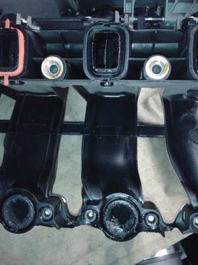
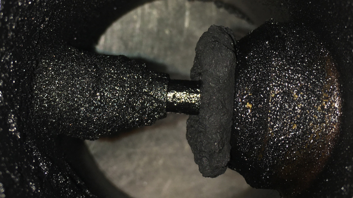
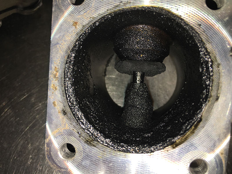
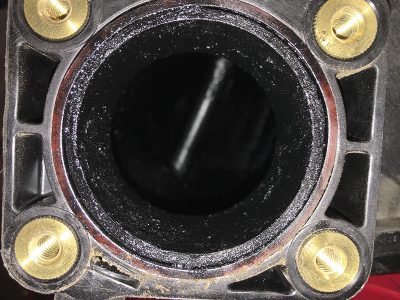
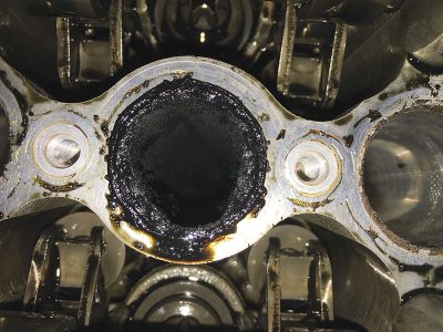
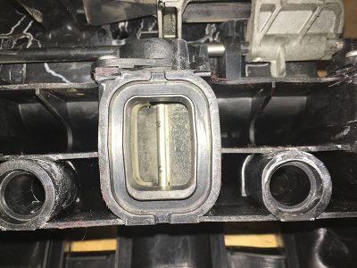
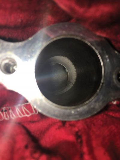
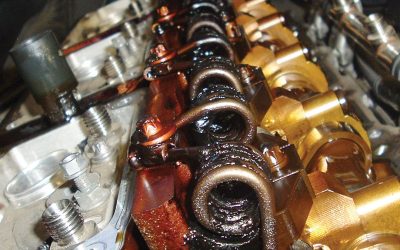
If you thought carbon buildup in the intake was bad on gasoline direct injected engines, imagine what happens when soot from the EGR system mixes with the oil from crankcase ventilation on a diesel. This is becoming a major problem. This issue takes place over a period of time ranging typically between 40,000 and 80,000 miles depending on vehicle operation and maintenance habits. The resulting reduction in performance is gradual, so not usually noticed by the driver. However, the disruption in air delivery will eventually be recognized by the engine management software in the DDE. This will result in the illumination of the “Malfunction Indicator Lamp†or “Check Engine Light.â€
The buildup of carbon creates a restriction in the air management system. If the resulting restriction is uneven across cylinders, this will cause uneven cylinder filling and power balance problems. Detection of this is similar to the crankshaft acceleration rate misfire detection on a gasoline engine. This will set cylinder-specific “roughness controller†faults (459C, 4593, 4596, 4592, 459B, 4595). In addition to these faults, the overall reduction in airflow will set plausibility faults for the air mass sensor (3FF1). It is not uncommon to also see plausibility faults for the throttle body and EGR valve.
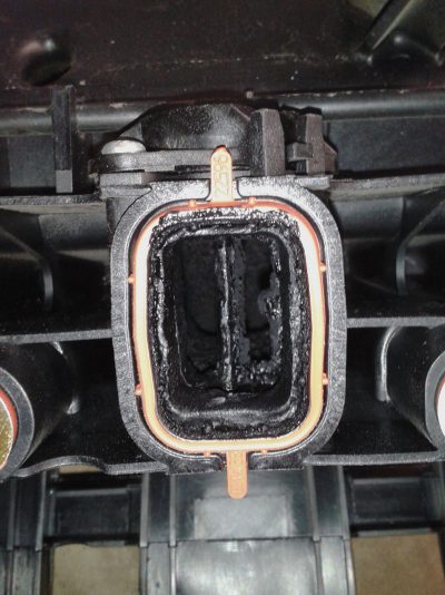
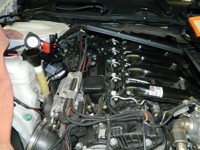
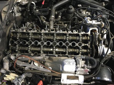
The fix is the same as on a gasoline engine, clean it. However due to the design of the intake on the diesel engine, this is significantly more labor intensive. You will need to not only remove the intake manifold, but also the valve cover.
When it comes to cleaning carbon from the intake, you typically have three options. Option one is chemicals. This process is still in its infancy within the industry. The problem here is that the carbon is a product of blow-by gasses and oil from the crankcase ventilation system mixed with soot via the EGR. It is then formed via heat and pressure.
Not all engines run at the same temperatures and pressures, as this will vary depending on loads. So every engine has a unique molecular make-up to the carbon build within. Don’t forget, with enough heat and pressure, carbon forms a diamond! So, because of so many variations, it is difficult to create a chemical that breaks down a such a wide variety of all the different potential chemical make-ups that can reside in the intake. And there can be significant variations from one manufacturer to another.
Option two is to clean manually using a combination of picks and scrapers. This method works OK but is incredibly time consuming. You will also not achieve the type of results that make before and after pictures look great. What you will achieve is a massive reduction of the restriction in the air management system. This will correct the drivability symptoms.
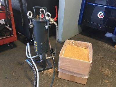
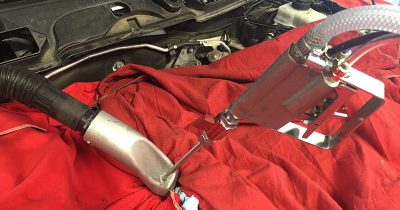
The last option is to use a blasting media in conjunction with a delivery method to clean the system. The media of choice is walnut shells, and the BMW factory tool (part number 81 29 2 208 034) for performing this walnut shell basting procedure is the best way to do it. This tool offers some additional features over generic gravity fed systems. The BMW blaster uses a pressure fed hopper to force the media solution into the distribution nozzle. It also uses a dual stage trigger, allowing the user to switch back and forth between walnut shells and just air.
In addition to the blaster, you will need specific adapters for the M57 engine (part numbers 2 356 966 and 2 356 967) and blasting wands (part numbers 2 356 968, 2 356 969, and 2 356 970). It is best to obtain an extra set of wands as you will find that making some modifications to them will give you more freedom to clean difficult-to-reach areas of the intake ports. For more information about the BMW carbon blaster and how to use it check out service information bulletin 11 03 14.
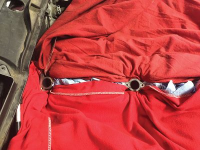
Before starting the cleaning process, take some time to cover and protect all open passages in order to prevent blasting media from going into locations that would be undesirable. Remember to only clean ports that have closed intake valves. You will need to turn the engine over by hand to complete the job and clean all ports. A special socket (part number 01 6 480) will be necessary for turning the crankshaft hub. The whole cleaning process will take some time, and you will use between 30 and 60 pounds of walnut shells depending on the severity of the buildup.
The intake manifold is also going to need to be cleaned Many service centers are simply replacing the intake manifold with a new one. However, the intake manifold can be successfully cleaned using a soda blaster. This is a blasting cabinet that uses baking soda as the abrasive media. Soda is soft enough to not cause any damage to the plastic or even the impregnated rubber seals on the swirl ports.
If you choose to use this method, completely disassemble the intake removing all the swirl pots, sensors, hardware, actuators, and replaceable gaskets before cleaning. You will need to clean the throttle body and EGR valve before reassembly. You can also use the soda blaster for this or use a good throttle body cleaning chemical. Be sure to keep any chemicals from flowing along the actuation shafts and entering the electronics.
When everything is clean and the parts have been reinstalled, there are a few things that need to be done before starting the engine. First, you will need to bleed the fuel circuit. Because diesel injectors open hydraulically, if the system is not bled the engine cannot start. There is also the potential for damage caused by running the high pressure pump dry.
Using your scan tool, there is a service function for fuel circuit bleeding. This function runs the in-tank pump while also opening the return valve at the rear of the high pressure fuel rail. The bleeding function is designed to clear out any air after replacement of the fuel filter. It will not clear out air trapped in the individual lines running from the rail to each injector.
To clear out this trapped air, crack open each line at the injector while the in-tank pump is running. You will see air bubbles exiting. Wait until you have a steady stream of diesel fuel and then retighten the line fitting. Perform this step on each injector. Obviously this will make a mess, so have some rags stuffed around the area and then clean everything up before starting the engine. Run the engine and check for any air, fuel, and oil leaks before installing the sound dampening cover.
Lastly, the “zero-mass adaptations†need to be cleared from the DDE. Failure to do this can potentially result in false cylinder specific faults. Prior to ISTA 3.47.10, this required an IRAP session to be performed at a dealership. The test plan has now been incorporated into ISTA. However, the vehicle must be programmed with ISTA/P 3.54.3 resulting in a target I-level of E89X-14-11-501 or E070-14-11-501 depending on chassis.


0 Comments