Making sure your rod’s charging system is up to running cooling fans and aftermarket electronic ignition. Plus, AWG, AC ripple, and spikes.
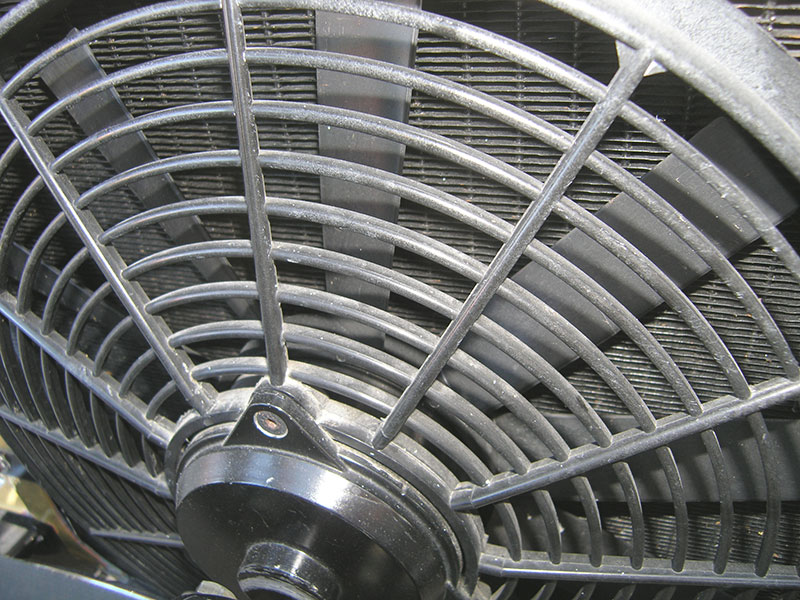
The blades on this electric fan are not particularly well designed to flow a large volume of air through the radiator. Always select a fan that with plenty of capacity for the application.
It’s common for vintage vehicles to be updated with modern electronic components, and one of the most important steps involved is providing the proper voltage and current supply for every one of these electrically-powered components. Two of the most common problems we’ve seen are a vehicles that have been updated with electric radiator cooling fans that have low voltage, are not properly installed, or are the wrong design for the application, and retrofitted electronic ignition that is not getting the correct voltage.
Electrocool
If you are experiencing overheating problems in a vehicle with electric cooling fans, the cause may be electrical connection problems or low system voltage to the electric motor that drives the fan. The fan will spin more slowly, thus flow less air, if a power or ground problem keeps it from getting the current it needs. You should also be aware that some aftermarket radiator cooling fan systems do a lot better job than others, but may draw more current than you might expect, so the charging system must have enough output at low engine speeds to cover the demand.
The horsepower of the fan motor, the design of the fan and shroud, and how the air flows through the radiator all affect how well the system will do in removing the heat from the coolant. The air should be able to flow through the radiator with as little obstruction as possible on both sides of the radiator. It is also important that hot air that has passed through the radiator can exit towards the rear of the vehicle and is not recirculated back toward the front. An engine that barely fits in its compartment can restrict the airflow out of the radiator so much that it cannot cool the engine properly. One possible fix that can increase the flow of hot air out of the engine compartment is to louver the wheel wells or the hood.
Adding electronic ignition
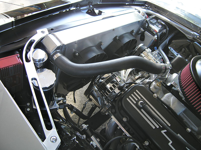
The cooling fans pictured here may flow a lot of air, but the radiator shroud does not draw the air through the radiator in an efficient manner.
A modern aftermarket electronic ignition system should function properly and dependably as long as the voltage available is above 12V, but if that decreases to 11.5V or less, coil output will begin to drop and some aftermarket and high-performance electronic ignition system modules will not trigger the spark properly. We’ve experimented with vehicles that had aftermarket electronic ignition systems where the voltage was below 11V at the coil. Typically, the engine would run roughly at idle, and we could both hear the engine misfire as well as see a high HC (hydrocarbons — an indication of misfire) reading on our exhaust gas analyzer. When we increased the system voltage back to the correct 14V, the rough idle smoothed out and the high HC reading dropped to a normal level.
Some aftermarket electronic ignition systems, such as the MSD Ready-To-Run distributors, are very voltage-dependent — if it gets below 12V, the electronic module may not function properly. The problems we’ve seen when system voltage at the module was too low have been such things as the spark being too advanced one moment, then too retarded the next, then as the engine rpm was increased to about 3,000 the spark advance suddenly jumped up 10 to 20 degrees with a rpm change of less than 100. These problems all disappeared once the system voltage was corrected to the 14 volts the system was designed to use.

A fan shroud like this allows the air flow to go through the whole radiator to maximize cooling efficiency.
Today’s high-energy and multi-spark c/d (capacitive discharge) ignition systems provide the spark plugs with a whole lot of ignition output, but that means they also need a very good and stable voltage source along with larger-gauge primary voltage supply wires and 8 mm spark plug wires with very good quality insulation. If you use 7 mm plug wires, or wires with poor quality insulation, the spark may find it easier to leak out to ground rather than jump the gap of the spark plugs. Also, every V8 engine has certain plug wires that are next to each other on the distributor cap and on the engine, such as cylinders #5 and #7 on a Chevrolet V8. If those two plug wires are run parallel to each other, the EMF (electro-magnetic force) that is created by the spark voltage passing through the wire can induce enough energy in the other spark plug wire to actually cause a spark to occur in the adjacent cylinder, igniting the air/fuel mixture at the wrong time. This problem can be avoided by keeping those plug wires away from each other using proper looms, or, if they need to cross each other, have them cross at as near to 90 degrees as possible.
| Alternator Output | Wire Length from Alt. to Batt. | Required Gauge |
| -Up to 70A |
Up to 10 ft. | 8 to 10 |
| 11 to 20 ft. | 6 to 8 | |
| 21 to 30 ft. | 4 to 6 | |
| -70 to 100A |
Up to 10 ft. | 6 to 8 |
| 11 to 20 ft. | 4 to 6 | |
| 21 to 30 ft. | 2 to 4 | |
| -100 to 150A |
Up to 10 ft. | 4 to 6 |
| 11 to 20 ft. | 2 to 4 | |
| 21 to 30 ft. | 0 to 2 | |
| -150 to 200A |
Up to 10 ft. | 2 to 4 |
| 11 to 20 ft. | 0 to 2 | |
| 21 to 30 ft. | 0 to 1/0 |
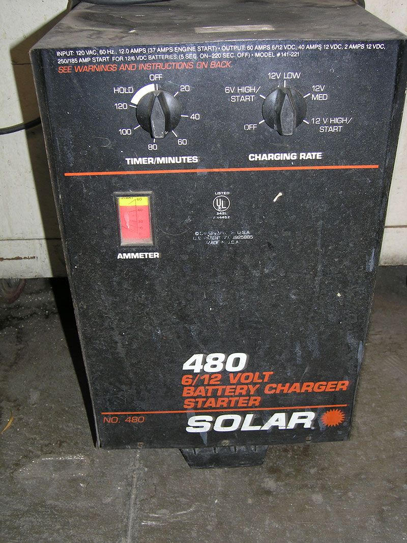
A battery charger operated in boost or start mode can cause voltage spikes that may damage modern electric components such as digital dash boards or electronic ignition modules.
As we discussed in Part 1 of this article, if the vehicle was originally equipped with contact points and a ballast resistor system (used to reduce primary ignition voltage from that of the battery to somewhere around 6V once the engine is started, which helps keep the points from burning up prematurely), it should be bypassed or removed when you convert the vehicle over to electronic ignition — you want the full 12.6V or the battery, then the voltage of alternator output, to feed the module directly. MSD offers a relay that can be used to supply the ignition system with full battery voltage on vehicles that originally used a ballast resistor, but you will still need a battery that has enough capacity to assure that voltage won’t drop too low during cranking.
AWG
The charging system of a vintage vehicle should have enough output to maintain 14.2V with all electrical devices turned on. System voltage should read the same at the output terminal of the alternator (B+), the battery positive post, as well as at every component that operates on battery voltage. There should also be no voltage drop on the ground side of any electrical component.
Use the AWG chart (previous page) to determine what gauge (AWG for “American Wire Gaugeâ€) should be used for the charge wire that goes from the output terminal of the alternator to the battery.
If the gauge of the any wire in the system is too small for the current that is flowing through it, it can lead to voltage drop problems and reduced current delivery to the circuit it is supplying, plus the wire may overheat perhaps leading to a fire. This same wire gauge guide should also be applied to both the power and ground connections on any electric circuit used in a vehicle.
Voltage Spikes
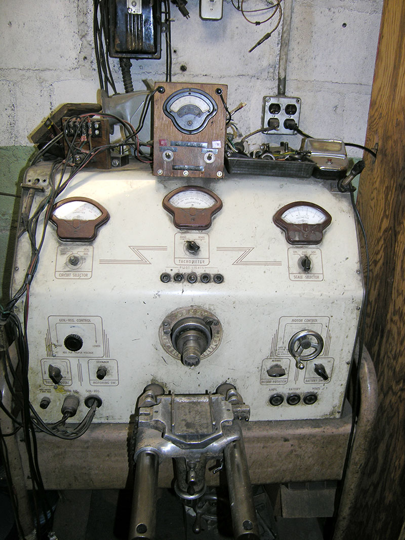
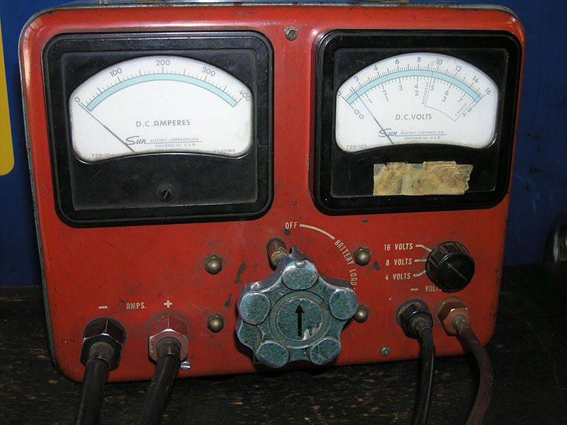
This is the vintage generator and alternator test stand we’ve been using since the 1950s. Still works.
There are no surge protectors in vintage vehicles, so care should be taken to avoid voltage spikes that can damage any modern electronic components that have been added. Among the things that can create voltage spikes are electric welding anywhere on the vehicle (TIG, MIG, or arc), an open spark plug wire, or one that falls off its terminal, or the use of a booster-type battery charger in start mode. But almost anything that creates voltage spikes, such as static electricity in very low-humidity ambient conditions, can damage the fragile solid-state components used in aftermarket electronic ignition systems, electronic dashboards, entertainment systems, or even the PCM of a modern fuel injection/engine management system. AC ripple voltage from defective alternator diodes must be kept below 5V, and a low-quality booster battery charger in jump start mode may deliver AC voltage in the 30V or more range when the DC voltage output is 15V while it is being used for a jump start.
Battery and Charging System Tools

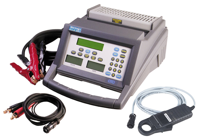
Here’s a modern alternator test stand that works even with today’s computer-controlled charging systems.
The tools we use to check vehicle charging systems include an old generator/alternator test stand, a vintage carbon pile battery tester, and some modern equipment from OTC/Bosch: an alternator and starter tester (“The Judgeâ€), a Minuteman Plus battery and charging system tester, a Smart Battery Tester, and a battery rest tool OTC # 3112 (used to reset the PCM when the battery is replaced on a vehicle with a computer-controlled charging system). We also use several DMMs (Digital Multi-Meters), dedicated voltmeters and ammeters, and an accessory belt pulley alignment tool from Gates (EZ Align). Probably the most important tools we need, however, is our eyes and experience. Use them to observe the big picture, and detect problems such as undersize wires, corroded power or ground connections, accessory belt alignment, air flow to and from the radiator, cooling fan operation, and all the other related problems you may have seen in the past.



0 Comments