

Welding basics are critical to ensuring corrosion resistance after collision repairs. We explore the corrosion implications of various welding settings including voltage, wire feed speed, stick-out, travel speed and other welding parameters.
Corrosion prevention begins with clean mating surfaces
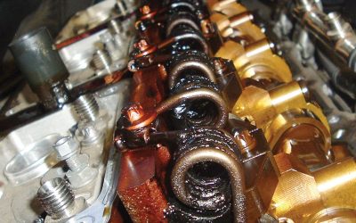
Attempting to apply welding or adhesive bonding techniques to metal surfaces on which there is dirt, oil, wax, rust, and (in the case of aluminum) oxide film creates a high risk of joint problems. This can include development of cracks, incomplete fusion, porosity and inclusion of contaminants. Each of these problems can lead to corrosion formation and weaken the welded joint.
Dirt, paint or other coating material not adequately cleaned off prior to welding can release corrosion-causing moisture when exposed to welding heat. These contaminants may also react with elements in the base metal to release hydrogen or other corrosive byproducts of such a chemical reaction.
If panels are adhesive bonded instead of welded, the adhesive acts as a sealer to keep corrosion-inducing moisture out of the joint. By preventing metal-to-metal contact, adhesives also reduce vibration and flex-caused stress cracks that can allow corrosion to start.
Before welding or adhesive bonding, remove old weld material, dirt, adhesive or other coatings from the existing part to prepare it for joining to the new replacement component.
Aluminum Oxide
Aluminum reacts with the oxygen in the air to form aluminum oxide, a thin film that covers the aluminum surface. The oxide layer can divert heat and prevent arc penetration to the root. This can result in a joint that, instead of achieving proper fusion or bonding, may have gaps and micro-fissures that allow corrosion to form. Additionally, oxide particles can become trapped on metal surfaces under the adhesive, or in the weld puddle as it solidifies. This can cause corrosion pitting, stress fractures, and ultimately lead to cracks and metal fatigue.
BMW recommends removing oxide film with a stainless steel wire brush or special sandpaper made specifically for aluminum. The stainless steel brush is preferred because it does not leave behind impurities that can become trapped in the solidifying weld puddle, where they can lead to crack formation or can release corrosion-causing moisture.
If you use special sanding or grinding material made for aluminum, do not grind too quickly, as that may cause smearing of the oxide rather than removal. Smeared material may interfere with welding penetration, and should be filed off prior to beginning the welding process. Make sure to clean off all remaining sanding grit or dust.
The replacement component may have residue on it from lubricants used in manufacturing, or coatings applied for protection during shipping and warehousing. The hydrocarbons in lubricants and some coatings can break down during welding and release hydrogen into the molten weld puddle. As the weld solidifies, this hydrogen comes out of solution and coalesces into bubbles, leading to porosity and potential entry points for corrosion.
Clean the mating surfaces with BMW cleaning agent R1. Do not use compressed air to clean off sanding or grinding grit. Compressed air lines contain moisture and oil that can contaminate the surface.
MIG/MAG Weld Only Over Bare Metal
In an area of at least 30mm around the weld seam or spot on the metal surfaces to be joined, clear off any paint, wax, grease, rust, dirt or other contaminants. Remove zinc (e-coat) if performing MIG/MAG welding, but not if resistance spot (STRSW) welding.
Also remove coatings from the reverse side of the weld area. If this is not done, contaminants could enter the weld puddle via the root during MIG/MAG welding. Similarly, paint or other coatings on the back side of a spot weld area could reduce electron flow, preventing an optimal spot weld.
Welding, or Weld-bonding?
In the narrow range of temperatures tolerated by aluminum and thin steels, welding requirements become more stringent. Some aluminum alloys or thin steel panels may not be able to accept welding heat without warping or altering their internal microstructure, and thus weakening the joint. Depending on the aluminum alloy, or the thickness of a steel flange or panel, welding may not be an option at all. Refer to the BMW repair information for guidelines on which joining method is best for a given aluminum alloy or thin steel panel.
Follow OEM Welding Parameter Guidelines
There are four main variables that control welding penetration and bead formation in the GMAW (MIG) process: welding current (amperage, determined on some equipment by wire feed speed), distance from welding tip to the end of the wire electrode (stickout), voltage (heat), and arc travel speed. To get the desired thickness and depth of penetration of the weld bead, you need to create the proper balance of these and other variables.
Because they’ve been validated by extensive engineering testing for the part and vehicle model being repaired, the OEM parameter recommendations are your best starting point for welding equipment settings.
Welding Current (Wire Feed Speed)
As you increase or decrease the wire feed speed (WFS) setting on your MIG welding machine, internal circuitry simultaneously increases or decreases the electrical amperage, or current. A combination of this current and voltage establishes the electric arc that connects the molten electrode (wire) to the base metal being welded.
There is a welding current (amperage) range that gives the ideal thermal profile to melt the base metal and deposit molten wire to fill the weld gap. Outside of this range, the filler wire behaves in ways that can harm weld performance.
Setting the wire feed speed (current/amperage) too high can result in excess heat that can distort and burn through the base metal. The burn-through risk is higher for aluminum, due to its lower melting point and high heat conductivity, and for thin sheet steels.
Excess heat caused by high wire feed speed can also result in distortion of the base metal in the surrounding heat affect zone (HAZ). Even slight distortion in the shape of the metal can alter its response to the load it was designed to handle, leading over time to stress fractures in the joint. Even if no collision or other excess load occurs to cause weld failure at these stress points, the fractures allow moisture to settle in the joint and become the starting point for corrosion.
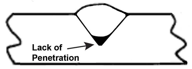
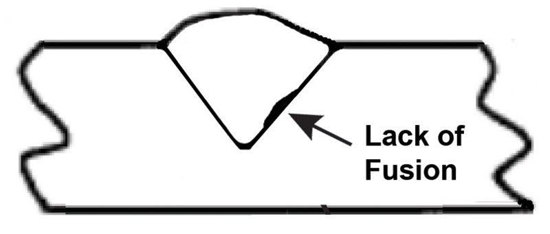
Too low a wire feed speed may cause a failure of the arc to penetrate to the base, or root, of the weld joint. The result is inadequate fusion, or tie-in, of the filler wire to the base metal. Any gaps in fusion can allow corrosion to take hold.
Wire Extension (Stickout)
In the MIG process, the collar at the end of the wire feed tube is what transmits welding current to the wire as it exits the tube. Stickout is the distance between the collar (contact tip) and the end of the wire electrode. As this stickout, or wire length, increases, amperage is reduced.
Fast travel speed (more on that later) and long stickout are great when using short-circuit transfer or inverter pulse welding on aluminum or thin steels. The current stays low enough to minimize the risks of too much penetration (burn-through) and/or heat warping of the base plate.
Too long a stickout results in wire being deposited with low arc heat. The wire will not be heated enough by the low arc temperature to tie-in, or fuse, with the base metal.
Instead, the molten wire will pile up on top of itself. It will absorb heat that the arc should be using to penetrate to the root or tie into the sides of the weld gap. Bead height will increase faster than width. The edges of the tall, narrow bead will roll over on one or both sides rather than fuse with the base metal. Again, the resulting gaps will allow an entry for corrosion.
Stickout is specified as a range based on the wire thickness and welding application. Less stickout generally results in a more stable arc, for better control over where in the joint the energy is being deposited so the desired fusion can occur. The shortest stickout within the specified range for the application will generate good fusion under low voltage operating conditions.
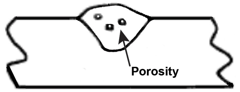
Additionally, too much stickout may stretch the shielding gas envelope so much that it thins out and loses ability to prevent atmospheric contaminants from entering the weld pool. This causes porosity and contaminant inclusion in the weld, both of which lead to corrosion.
Stickout plus arc length equals tip-to-work distance. Maintaining a relatively constant contact tip-to-work distance (CTWD) is important. If you change the tip-to-work distance, arc length (arc voltage) will change, and that will alter weld bead shape and performance. This is determined by Ohm’s Law, which says that if current (set by wire feed speed) is held steady, an increase in voltage causes an increase in resistance, making the arc hotter. So, lengthening the arc increases heat and leads to a wider, flatter bead. Shortening the arc results in a narrower, taller bead.
Be careful not to use too short a tip-to-work distance. Some wires are shipped with lubricant residues left over from manufacturing, or coatings that are intended to protect the wire during shipping and warehousing. With shorter stickout, less resistive heating is available to evaporate these residues, and they can enter and contaminate the weld pool, increasing corrosion risk.
Voltage
The voltage setting on MIG welding equipment influences the shape (height and width) of the weld bead. Insufficient heat causes failure of the filler metal to fuse completely with the base metal.
Grooves may form beneath the surface, where the heat failed to penetrate deeply enough to fuse the bead to the desired depth into the base metal, or even to a previous weld pass. Called “undercut grooves,†they create a place where moisture may settle in the weld, leading to corrosion.
Too much voltage (heat) can also cause undercutting. When voltage is too high, the arc spreads the molten weld pool, resulting in reduced heat transfer to any one area. The outer edges of the weld puddle cool faster and remain separated from the base metal rather than fusing with it. Rather than a smooth transition of the outer edges of the weld bead to the adjacent base metal, you may see areas in which the weld metal shows a lip, or overlap of the base metal. In addition to being a weak joint, this undercut groove offers an area for corrosion to set in. Additionally, too much heat causes excessive spatter and a misshapen weld bead, which at the least requires additional rework to improve finished weld appearance.
Dancing Together Voltage, Wire Feed Speed and Arc Length
Boiled down to the simplest explanations, voltage influences weld bead shape (height and width change independently of each other), wire feed speed controls bead size (height and width can grow or shrink by the same percentage), and arc length impacts weld fusion.
If the weld bead is tall and narrow, increase voltage. If there are gaps (undercutting) between the bead and base metal, decrease voltage.
If the bead is too small, or if there is inadequate weld penetration, increase wire feed speed. If the bead is too large and, instead of fusing with the sides of the weld gap (or with a previous bead if you are doing a multi-pass weld), overlaps the gap edges, decrease wire feed speed.
For welding thicker plates or wider gaps, increase arc distance from the base metal. You’ll get a hotter arc which, if travel speed is not too fast, results in greater penetration and a wider, flatter bead. Shorten the arc to get less heat and a narrower bead with greater metal accumulation
For a weld that has uniform thickness from start to end, voltage, wire feed speed and tip-to-work distance should all be kept at the same relative
values to create a durable and attractive weld. You should do test welds to determine the best settings for each of the parameters for which your welding equipment allows adjustments.
Travel Speed
As you travel the arc along the joint you are welding, the heat needs to reach down to the root of the weld gap. If you move the arc too quickly the heat does not penetrate deeply enough to fuse the panels together completely. They may be fused at the top, but have a gap or only a weak blending together at the bottom.
A gap provides an entry for moisture and corrosion. A weak joint is a risk factor in the event of a future collision.
What you will see if you travel too quickly is a narrow weld bead with a pointed crown that is taller than the bead is wide. You should instead see ridges that are gently curved and leaning on each other, like a stack of coins laying on its side.
Travel too slowly and you also end up with incomplete fusion. Not traveling quickly enough allows some of the molten wire to pile up in front of, and to the sides of, the arc. This excess molten wire absorbs some of the heat of the arc, preventing the ability of the weld puddle to fuse at the toes (sides), or at the root of the joint.
What you will see is sharp edges on one or both sides of the weld, rather than the desired smooth transition from weld to base metal. If you crosscut the weld, you will see gaps and microscopic fissures where the filler wire did not fuse with the base metal.
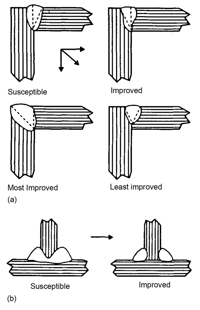
Walking the Puddle
Training your dog to walk slightly behind you establishes your control. Keeping the arc on the leading edge of the weld puddle as you move forward allows heat focus for maximum weld penetration. If you need only a narrow bead, move straight ahead while keeping the arc in front of the puddle.
If you need to fill a wider gap, move forward in an upside down “V†pattern. Starting on one side, move up and toward the center of the gap, then back down and to the opposite side. Move further forward, repeating the pattern in the opposite direction. Keep the narrow end of the “V†in the center of the gap. Pointing the “V†in the direction you are welding creates the familiar “stacked dimes†appearance of a successful weld fillet. Pause briefly at each side to allow fusion to occur.
Reversing the pattern so the arc moves with the open end of the “V†facing forward focuses heat on the outside edges, or legs, of the joint. Not enough heat makes it to the center of the joint to penetrate to the root. You can see the effects of this in a cross-section of the finished joint. There may be fusion at the outside edges, or toes, but a gap at the root, where the arc failed to bite into the base.
In the event of a future collision, this gap could be a weak point that causes a larger failure. Just one failed weld could prevent a crumple zone from performing as intended. Even without a collision, this gap could allow moisture to seep into the weld, leading to the formation of corrosion.
Choose the Right Shielding Gas
Shielding gas, along with current and voltage, provides major influence over the behavior of the heated filler wire and, ultimately, the shape and strength of the weld bead. Shielding gas prevents the entry of oxygen, nitrogen, and hydrogen from the atmosphere into the molten weld puddle. These atmospheric elements can cause a variety of problems that limit the strength and durability of your weld.
For example, nitrogen in a steel weld can cause microscopic cracking that, in addition to reducing the impact resistance of the repair, creates an opening for corrosion-causing moisture to settle in the joint.
Too much oxygen absorbed into a steel weld combines with other elements in the metal and alters the weld microstructure in ways that weaken the repaired area. The excess oxygen can combine with carbon to form carbon monoxide, a gas that will leave pinholes in the metal as it bubbles out of the cooling weld puddle. In many cases, this porosity can extend from the surface all the way down to the root, making it easy for corrosion to set in and quickly damage the weld.
Hydrogen, extracted from water vapor in the air by the welding heat, can combine with the iron in steel and cause microscopic cracking to occur in the interior of the weld bead. Hydrogen can cause microscopic cracking in aluminum, too.
Three main gases: argon, helium, and carbon dioxide, sometimes in combination with small amounts of oxygen or other gases, are used to shield the weld puddle from atmospheric contaminants. Different shielding gas formulations are used with various electrode wire types and metal transfer methods (short arc, globular transfer, or spray arc/pulsed spray arc welding).
OEM-recommended gas and wire duets
The shielding gas used must be matched to the electrode (filler wire) and base metal. If you do not use shielding gas that is compatible with the required filler wire, porosity and microscopic cracking may weaken the weld and open the door to corrosion.
For MIG welding mild steel using solid wire, the recommended shielding gas is often a 98 percent argon/2 percent oxygen formulation, while for aluminum, it is 100 percent argon. When welding mild steel using flux-cored wire, an approximately 80 percent argon/20 percent CO2 shielding gas produces a more stable arc with less spatter, for a better quality weld.
Your BMW repair procedures information will specify the correct filler wire type and shielding gas combination for the base materials being welded.
For example, when MAG welding steel components on the 535i, BMW specifies one of two types of steel welding wire: G3Si1 (SG2) or G4Si1 (SG3), along with shielding gas composed of 82 percent argon, 18 percent CO2. The addition of CO2, which has a minor chemical reaction with the molten weld puddle, makes this a MAG (active) welding process. The CO2 produces a more stable arc, making it easier to control weld penetration and avoid incomplete fusion and gaps that allow corrosion to get a toehold in the weld.
Match Filler Wire to Base Metal
In addition to making sure the wire and shielding gas are compatible, you must match the filler wire to the base metal being welded. If the filler wire and base metal are significantly different, even when properly welded together, they can form a galvanic reaction that leads to corrosion within the welded joint. Vehicle manufacturers recommend specific combinations of filler wire and base metal based on extensive testing that assures that the completed weld will not only meet strength and durability requirements, but will also resist corrosion.
TIP: Store filler wire in sealed containers in a dry place until you are ready to use it. Some wires can absorb atmospheric moisture into their coating. Welding heat then helps to vaporize and release the moisture. Because the wire is inside the shielding gas envelope, any moisture vapor or other released gases can enter the molten weld pool. Some of these vapor bubbles may make it to the surface of the weld pool before it solidifies, while others remain trapped inside. It may turn your weld bead into something resembling swiss cheese, with microscopic holes in the interior and pinholes on the surface. Each hole creates an opportunity for corrosion to begin.
Done with the proper welding and bonding materials and techniques, you’ll be able to replicate, as closely as possible, the strength and durability of the original structure. And, at the same time, you’ll be joining components in a way that will, in the future, resist rust and corrosion and will allow your customers to continue to enjoy the reliability they’ve come to expect from their BMW.
Download PDF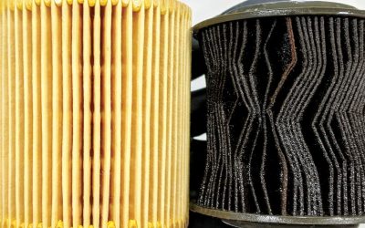
0 Comments