Carbon fiber reinforced plastic (CFRP) is showing up on more Mercedes-Benz models as the company reduces weight. We provide a few tips on what to look out for when repairing CFRP components.
Why carbon fiber?

The carbon fiber rear diffuser on this 2019 AMG GT 4-door Coupe may be repairable, but only if damage is either limited to minor surface scratches, or is hidden out of view on the bottom area of the part.
For decades, Mercedes-Benz engineers have been working their magic to extract additional fuel economy from engine and drivetrain improvements. The company is now harvesting further efficiency advances from vehicle weight reduction. Pioneering the use of new composites and alloys, Mercedes-Benz is replacing traditional steel with carbon fiber, aluminum, and other light materials. They offer a superior strength-to-weight ratio while allowing significant weight reduction, often with improvement in structural integrity.
Carbon fiber is five times stronger than steel, twice as rigid, and lighter than aluminum. It is far less vulnerable to corrosion than metal. And, it offers molding flexibility that allows manufacturers the freedom to create components that are both functional and take vehicle design in exciting new directions.

The interior of the 2019 AMG C 63 coupe includes carbon fiber accents in the dash, steering wheel, center console, and other areas.
Composites are created from two or more materials, which, when chemically joined, form a product that offers tensile strength that exceeds that of the individual materials. Carbon fiber reinforced plastic (CFRP) is a composite made of strong, lightweight carbon filaments that are embedded in an epoxy resin. The strength of the composite is maximized when you have the proper ratio of resin to fiber, typically between 40% to no more than 50% resin. The carbon fibers give the component greater strength at lower weight than steel or even aluminum.
Basic CFRP manufacturing concept
The manufacturing of CFRP is simple in concept, but has very sophisticated variations of formula and process to achieve the performance objectives of different vehicle applications. The simple concept involves three basic steps:
- Combine carbon fibers and epoxy resin in a mold. When creating a CFRP component from scratch, the mold is what gives the piece its shape. Repair is slightly different, and will be discussed later in this article.
- Using vacuum, extract as much resin as possible out of the mold. Extraction accomplishes three goals. First, it draws liquid resin through the reinforced fiber mesh. This helps ensure that each individual carbon fiber is coated with epoxy resin, which adhesively bonds it to nearby fibers, reinforcing the already high strength of the material. It also removes air and eliminates voids (empty areas) in the mesh. Without air or voids, the cured resin becomes a solid enclosure, called a matrix, which further strengthens the embedded carbon fiber material. The adhesive coating also protects the carbon fiber, which is somewhat brittle, from potential damage during the buildup and curing processes. Second, the vacuum helps draw the CFRP mat into the shape of the mold, or in the case of repair, presses and holds the carbon fiber patch into the cutout area during the curing process. Third, vacuum extraction removes excess resin from the component. This helps create the desired 40/60 ratio of resin to fibers, giving the ideal strength and performance profile to the finished CFRP component.
- Cure the carbon fiber component by holding the assembly in vacuum over the manufacturer-specified amount of time. In addition to coating the fibers with epoxy resin, removing air, eliminating potential voids in the carbon fiber mesh, and extracting excess resin. The vacuum keeps the fibers in place in the resin as it cures.
The above three-step list is a simplification for explanatory purposes only. Refer to your Mercedes-Benz Workshop Information System (WIS-net) on the startekinfo.com website for repair information specific to the vehicle and CFRP component on which you are working. You can access an extensive library of documents explaining repair procedures for fiber composites by entering the VIN for a Mercedes-Benz SLR McLaren (model 199) in WIS-net.
The repair difference

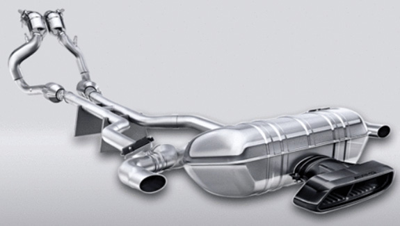
The cover for the exhaust tailpipe on the AMG GT S is made of carbon fiber. It protects the rear diffuser (lower bumper cover) from high exhaust temperatures and contributes to the aggressive, racing profile of the vehicle’s rear end.
It is important to remember that while the original component is one piece, any repairs depend entirely upon a well-planned and executed adhesive bond to approximate the strength and structural integrity of the original part.
Non-structural CFRP components may be patched in a manner similar to the repair of sheet molded composite (SMC) plastics, if the damage is minor. Grinding out the damaged area with a gradual taper instead of a vertical cut increases the surface area where the original component and the replacement patch will mate. This increases the strength and durability of the repaired part.
The stronger the repair needs to be, the more gentle the taper must be, to create more surface area for the edges that will be bonded.

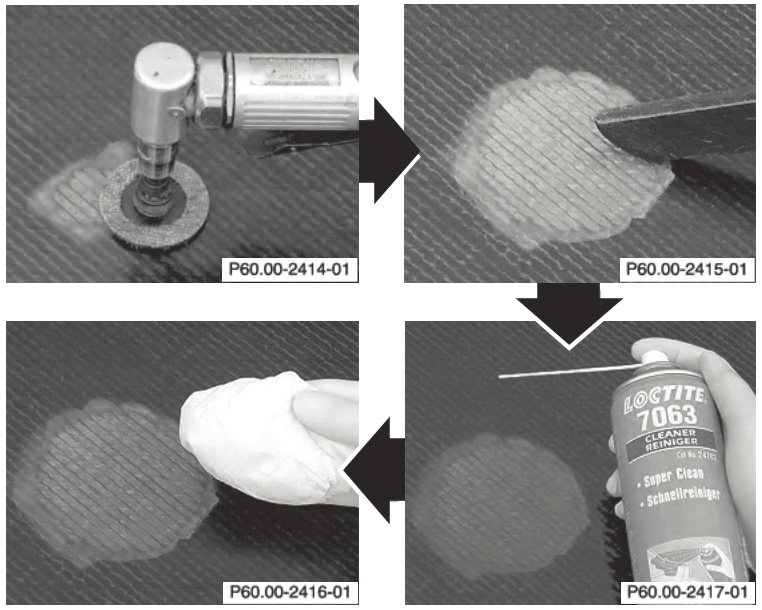
Two things are key when repairing minor surface damage to carbon fiber components. First, do only light sanding, and use sanding disks specified by Mercedes-Benz, to reduce the risk of grinding too deep into the fiber composite layers. Second, clean, clean, clean. Use a wet/dry vacuum to remove sanding dust, then clean the fiber composite surface at least three times with application of fresh degreasing agent each time. Never blow shop air over the surface, as even a tiny amount of oil from your air supply can prevent the epoxy resin from curing properly.
Mercedes-Benz repair instructions for the CFRP component will typically indicate the desired taper by specifying that you cut in steps so that the opening becomes progressively smaller in diameter as you cut into the composite material. As you rebuild back out, each new layer of replacement carbon fiber mat is slightly wider until you have restored the original thickness of the material. This creates a taper that expands the total mating surface area, and creates a more three-dimensional (top, bottom, and sides) bond. It also helps create a patch that duplicates the thickness and density of the original component, and gives superior resistance to post-repair movement, laterally or vertically, of the patched layers.
Damage is not always visible on the surface
Collision impact, bending stress, or other damage can significantly reduce the strength of a CFRP component. Unfortunately, CFRP components can suffer impact damage that, while severe, is not visible on the surface. Fibers may be cut, frayed, or separated, but not visible because they are underneath a top layer of uncut fibers. Similarly, horizontal (laminate) layers in the mat can separate, and yet the gap remains invisible because the surface layer was not disturbed.
There may be many thousands of individual filaments in a single carbon fiber, and many fibers in a carbon strand or ribbon that is woven into the CFRP mat. As an electrical cable can no longer carry its rated current capacity after a certain percentage of the individual wires inside its sheathing become broken, a carbon fiber strand or ribbon can no longer support its rated load capacity after a number of its filaments or fibers are broken or separated from each other.
No repair of structural CFRP components
Any of these types of damage weaken the carbon fiber material. For structural CFRP components such as those that are part of the honeycomb monocoque body of the Mercedes-Benz SLR McLaren supercar, any damage beyond superficial surface scratches requires replacement of the complete component. Minor surface scratches may be buffed out and refinished, but anything more extensive cannot be safely repaired. Replacement is mandatory for any structural CFRP components that have suffered weave damage.
Non-destructive testing
Regardless of whether the component is structural, an exterior panel, or an interior accent, you must determine if there is any significant internal damage before attempting to repair a CFRP part.
A Mercedes-Benz -approved Fiber Composite Tester uses special sensor technology to “see†breaks and other anomalies in subsurface carbon fibers and the resin base in which they are embedded. However, no non-destructive test is guaranteed to detect 100% of damage, especially any that is below the surface. If for any reason you suspect there is subsurface damage to a structural component, even if testing does not confirm it, that part must be replaced.
Non-structural components, including exterior panels and interior accents, may be repaired, depending on the location, type, and extent of the damage.
Exposed or non-exposed weave?

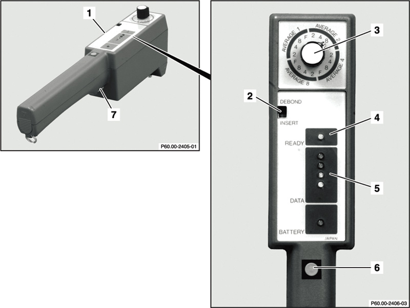
The fiber composite tester approved by Mercedes-Benz shows the degree of damage it found by illuminating different color lights in its display (#5 in the image). Damage affecting less than 8% of the fiber composite material illuminates a green light, and 8% – 16% sets a yellow. The next three levels indicate damage found on up to 40%, 80%, and greater than 80% of the composite material. These result in increasing intensities of red lights, signaling the difference between damage that may be repaired with minimal or moderate amounts of effort, and that which can more efficiently be addressed by replacing the entire component.
There are two types of carbon fiber in terms of the visibility of the fiber weave. Each is based on a woven matt of carbon fibers that are embedded in an epoxy resin or other polymer-forming compound.
For one type, called “exposed†weave, the resin is clear or slightly tinted, allowing the weave pattern to be visible through the clearcoat. The other, “non-exposed†type features similar woven matte technology, but receives a solid color topcoat. The weave is not visible under the finish of this non-exposed carbon fiber material.
Because they are woven, both types of carbon fiber require specialized repair for anything beyond minor surface scratches and nicks. Once a composite material’s threads are broken, the individual carbon fibers cannot be re-woven, or “spliced†back together.
You may be able to grind out the damaged area and insert a replacement section of carbon fiber mat, but if it is done on an exposed weave material, a discerning customer may not be happy. Even a really good butt joint created by gluing together two cut edges of an exposed weave carbon fiber panel would likely remind you of a pocket on a patterned shirt; the seam is almost, but not quite invisible.
Damage is slightly less of a problem with carbon fiber that features a non-exposed weave pattern. Working from the underside of the component, you’ll grind out the damaged section and replace it with a new piece of the same weight and weave type.
After sanding to smooth out the surface, applying the solid color topcoat will make the seam edges invisible.
Dry or wet layup?
There are two basic ways to build CFRP components. Both can be done in a collision repair facility environment, but one is used extensively to construct parts from scratch, while the other is the primary method used to repair damaged CFRP components.
To build a CFRP component from scratch, you add liquid resin to a carbon fiber mat in a mold, press it through the mat and then squeegee or, using vacuum, pull as much resin as possible out of the mold before curing. When done this way, it is called a “wet layup.â€
To repair a damaged CFRP part, you grind out the damaged area (or areas), and add to each damage area a new carbon fiber patch that has been pre-impregnated with an epoxy resin. The “pre-preg†mat is placed in the cutout area, excess resin is forced out via vacuum, and the piece is cured over a specified number of hours. Done this way, the process is called a “dry layup.â€
The dry layup method is easier to use in the field. It wastes less resin, is less messy, and depending on the type and size of the finished component, can be cured without the application of heat.

The “dry layup†CFRP repair method uses carbon fiber patches that are pre-impregnated with epoxy resin to repair the damaged area. Vacuum is applied to help infuse the resin through the patch. Layers of perforated film are placed on the top and bottom of the composite material to allow excess resin to be drawn away from the panel (#1 in this image) for disposal after curing. Plastic is taped around the damaged area (#6 in this image) to seal it for application of vacuum. To prevent the plastic from sticking to the patch and causing an uneven distribution of the epoxy resin as the vacuum draws it out, there is a vacuum mat (the white material in this image) that functions as a spacer between the plastic and the patch. A valve is punched through a hole in the plastic, to allow vacuum to be drawn.
Repair strategy depends on extent of damage
Types of carbon fiber material damage that require different repair methods include, but are not limited to:
- Surface damage, one side only
- Holes in the fiber composite, single-layer design
- Holes in fiber composite, sandwich design
- Damage at the edge of a composite panel
- Separated laminated layers
- Separated flange connection between fiber composite panels
Mercedes-Benz offers application-specific repair instructions for each of the above-mentioned types of damage to carbon fiber components. You can find the factory-approved repair procedures by looking up the damaged component in WIS-net by year, make and model of the vehicle.
No substitutions
The base carbon fiber material can feature any of a variety of different weights, weave patterns, and surface finishes, depending on the intended application. For example, carbon fiber materials are available in different filament densities, or weights, measured in ounces per unit area (width times length) of fabric. Heavier fabric tends to be stronger, but may also be less flexible for molding into shapes with multiple angles or deeply curved surfaces. Different weave patterns also offer varying combinations of strength, pliability for molding and shaping, and appearance of the finished surface. The net for collision repairers is that you cannot substitute different types of carbon fiber willy-nilly into a repair.
Temperature and humidity
The epoxy resin must be cured in a specified range of ambient temperature and humidity. If it is not applied and cured within the required ranges, the repair will not achieve its desired strength and durability. The epoxy resin manufacturer will include the required temperature and humidity ranges in their application instructions.
To document that the adhesive was applied correctly, Mercedes-Benz requires its technicians to record the ambient temperature and humidity at the start and through the duration of the curing process.
Less aggressive sanding for carbon fiber
Refer to the paint manufacturer’s technical data sheets for recommendations on the proper sanding medium. This is critically important when working on carbon fiber components in which the fiber weave is visible in the substrate, such as on the Mercedes-Benz AMG GT. An overly-coarse sanding medium, or too aggressive a sanding application, will result in the clear coat and other top layers being degraded, and some carbon fibers becoming exposed. Once any carbon fibers are torn and exposed, the CFRP component is structurally weakened, and must be repaired or replaced.
Contaminant avoidance
Carbon fiber surfaces must be contaminant-free in order to allow formation of a strong adhesive bond with whatever component to which they are being joined.
Additionally, avoid using compressed air to dry or cure primers, fillers, or adhesives. Even tiny amounts of oil in the shop’s compressed air line can contaminate the CFRP substrate and reduce the strength of an adhesive or other bond. Follow the manufacturer’s instructions for the correct process to dry or cure any coating or adhesive on the CF component.
Carbon fiber explosion risk
Carbon fiber dust is combustible, and can explode when in the presence of a spark. You’ll need a dust extraction system, and a separate, enclosed workspace for repairing CF surfaces.
Pretreatment of bonding surfaces
Surfaces to be glued must be free of contaminants in order to achieve a strong connection between the glue and the parts to be connected. Brush or, if on metal surfaces, grind away dirt, rust, and paint residue.
If bonding aluminum to a carbon fiber component, make cleaning the aluminum one of your last steps before applying the adhesive. Aluminum reacts with air to form a thin skin, called an oxide layer, which will prevent primer, adhesive, or other coatings from developing a long-term bond with the metal surface. An oxide layer begins forming whenever aluminum is exposed to air, so plan to clean and then apply primer, adhesive, or other coatings immediately after grinding away any oxide or other contaminants on aluminum surfaces.
Cleaning requires two steps to ensure a strong bond. First, any grease that has transferred to metal surfaces from tools, compressed air, or even body oils from your fingers must be removed. You can degrease surfaces with carbon tetrachloride or trichlorethylene.
Always follow the procedures recommended by Mercedes-Benz, and by the glue manufacturer. For example, if the glue is a two-part adhesive, use only the bonding agent specified, and adhere to the recommended flash-off time. Follow these guidelines, and your carbon fiber repair will be masterful.
Download PDF 〉


0 Comments