Part 1
For the uninitiated learning technicians and, yes, you can teach an old dog a new trick.
The vehicle tested was:
- VIN: WVWHD7AJ8DWxxxxxx
- Make and model: 2013 VW GTI
- Engine: 2.0L DOHC TFSI (CBFA)
- Sales code: 5K19W3 < Narrow down the information to the vehicle
Notes of a tech call
The story begins with a technical support call from a repair facility that was having a problem with an EVAP fault. It was noted that a few weeks before, the vehicle passed the mandated emissions test. The ECM fault directed the technician to a possible EVAP solenoid fault/defect. Freeze frame data indicates the fault was recorded well after the emissions test was completed.
(Fault 1) P0458/001112 – EVAP System Purge Control Valve (N80): Short to Ground
For the sake of clarity, an aftermarket and an OEM solenoid were replaced and tested. The original EVAP solenoid was defective and did not pass the resistance test (shorted). The VW emissions test was now run with VCDS while in the service bay (readiness) with the replacement solenoids.
The group for basic settings is 070 and a passed test should indicate EVAP OK in field 4.
Multiple failed tests
Assumptions get made but a resistance test on both solenoids proves that both replacement EVAP (N80) solenoids pass one test.
Test Purge Regulator Valve (N80) terminals 1 & 2 for resistance.
Specified value: 15.0 to 25.0 ohms.
Turn the ignition switch ON and look for the supply voltage. That test should also pass.
Hint:
Low resistance readings indicate a cool part.
High resistance readings indicate a warmer or hot part.
Apply battery power and ground with the correct connections, the solenoid should react by opening or closing the port along with audible clicks.
Basic settings in this case failed twice and a new fault is set.
(Fault 2) P0444/001092 – EVAP Purge Control Valve (N80): Open Circuit
Schematics of different versions (OEM or other schematic)
From the inexperienced point of view – now what!
All of the known tests have been done and most folks generally view the last statement “Replace with known good part†as not the best solution. Measure it first and use Ohm’s Law.
Schematics do come in many flavors and at times simple is better. In this specific case, an OEM version was sent and requested the pages to be printed. One question was asked: “Do you know how to read current tracking schematics�
Solenoid N80 is indicated at the bottom of the first schematic. The bottom row numbered 155 to 168 is the current track. All pages are current tracked in a manner that corresponds to connections on other matching pages. The number 49 on this sheet corresponds to current track 163 (make a line straight down to match from 49 to track 163). Follow the next corresponding pages at the bottom to find 49 in the current track.
Number 49 connection corresponds to the next image with current track numbers 43 to 56. Align number 49 at the bottom of the second sheet and connection 163 lines up (make a line straight up to match track 49 to 163). At connection D180, find fuse SB24 and that will be the positive power connection to feed pin 1 at solenoid N80.
This is how VW and Audi schematics work and nothing crosses over to avoid any possible confusion.
Pin 2 of solenoid N80 is the ECM control side (ground activation via engine management). T60/35 of the ECM means: At the harness connection, it is identified as a 60 Terminal connection and 35 is the numbered terminal position connecting N80 pin 2.
For the uninitiated, print the set and lay them out. For black and white schematics, crayons are great to color powers, grounds, illumination or controls. Highlighters will work, and have a pencil/pen ready to write the test values on the pages in question. The schematics for this model are in color.
Step by step with the technical call.
The technical call included:
- Ensure the resistance test passes at the solenoids.
- Load test the EVAP solenoid and calculate the voltage drop to the positive side pin 1.
- Test the control side between pin 2 of N80 and the ECM with a multimeter.
Reconnect the system.
With VCDS and at function 03, perform an output test for N80. Audible clicks should be heard. With the VCDS test operating, the test failed and the “Open circuit†fault for N80 is recorded immediately by cycling the ignition key.
Two distinct tests proved (a) the VCDS output test was looking for a result and (b) the engine management system monitored a failed connection when the key was cycled with or without the VCDS output test. Engine management systems do their own on-board and component tests with a key cycle (most times).
There was no audible sound using the output test with VCDS. Now the tech begins to understand the power of bi-directional control.
The last test to perform with the technician was to back probe (correctly) and close the ground circuit for the solenoid N80 at the ECM. Ground that terminal with KOEO and listen for the audible click. The tech is now beginning to learn Ohm’s Law and learning to control a solenoid.
The ECM in this case is still within warranty. To quickly solve the customer’s problem, the technician was directed to bring the notes, schematics, defective EVAP solenoid and the vehicle to speak with the dealer technician tasked to solve this issue.
I wonder how much that dealer tech was paid when it was all played out for him?
What was learned? Although not 100 percent, it is believed a defective solenoid N80 damaged the control circuit of the ECM. The replacement ECM will require an immobilizer adaptation and, since it fell within the warranty period, it was replaced at no cost to the vehicle owner.
And the point is?
The point being, an EVAP, Secondary Air, Switching vacuum valve, EGR control or boost control, are generally tested in the same fashion using the above directions.
Part 2
The magic wand
Testing the EVAP with an oscilloscope and using VCDS
| Tools needed |
| 90 amp floating power supply |
| Ross-Tech VCDS |
| Oscilloscope, attenuator and a magic wand |
| Wiring schematic |
| Back probes and simple connection harness |
Part 2 continues
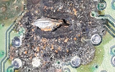
There was a damaged part that was destined to be trashed but scavenged with some curiosities about the magnetic properties of a switching coil. What can I do with it? How about repairing the damage and attaching an oscilloscope for a few experiments?
A switching coil can mean an EVAP solenoid, Secondary Air solenoid, EGR solenoid or Boost Control solenoids.
The mystery of the part will be revealed in another article. Just think about it for now.
For these simple tests, any coil will do, but found a few different versions to test and apply some theories. These theories, however, turned out to be natural laws that are applied within this trade/profession.
Note: Anything with a steel cover will not work with the applied test.
The next image is of a VW Beetle 2.0L fuel injector, back probed with an oscilloscope attached via Bluetooth to a tablet. (Back probed meaning voltage acquisition over time.)
Back probing also means that a 20:1 attenuator must be used or definite damage to the oscilloscope is likely. The inductive kick is the damaging property. The cable attached to the oscilloscope has a 10:1 probe, with the 20:1 attenuator equaling 30:1 in total.
Note: A classic image of many port injected models, and captured in the perfect moment. This should be considered as normal in many vehicles with port injection systems.
What if a measurement is tested at a “change over solenoid†(EVAP Purge, Secondary Air, EGR, Boost Control, etc., etc.)? The majority of solenoids have a plastic shell that surrounds the solenoid windings. This is where the coil and plunger reside, similar to many applications.
- The solenoid has two connections, one positive and one negative.
- The test can be accomplished on the vehicle or on the test bench.
- The vehicle test requires a ground circuit or with a scan tool’s bi-directional control.
- This specific solenoid on the VW controls the EVAP function.
- Simply, the ECM controls the vacuum source via solenoid to allow the EVAP gases to pass through. The opposite end of that port can be measured with a simple vacuum gauge that is “teed†at the control side. Opening or closing the solenoid (controlling ground) will control vacuum to purge the EVAP. If the solenoid opens and allows gases to pass, the O2 sensors will react to the rich condition. Monitoring the front O2 sensors with an oscilloscope proves how the engine management system works and is in control.
Remember that many EVAP systems have more than one solenoid attached to the system and BOTH work in harmony with each other.
On the bench test, it is measured (back probed the negative side) and grounded the circuit three times. Battery positive is applied at all times. Of course, correct polarity is applied.
The following image is of an operating solenoid (change-over valve), appearing similar to a port fuel injector waveform with three pulses.
The spike (inductive kick) is noticeable on this image and nearly identical to how a fuel injector works.
The inductive kick meaning
When battery voltage or a control circuit disconnects from an inductor (in this case a solenoid or injector) the inductor will inherently maintain current flow because current cannot change in an instant. A coil takes time to build the magnetic flux but the rapid decrease or collapse (disconnected circuit) through an inductor releases the stored energy as a magnetic flux, to a voltage.
The next image is with the “magic wand†made for the experiment.
Abracadabra – the magic wand tells a story.
The yellow trace offers the “quick look†(green is turned off) and abracadabra!
With both traces visible, one can see the similarity with the green over the yellow trace. Part of the accomplishment was taking a damaged part and re-purposing it as a tool. Another part of the accomplishment was measuring that same “magic wand†against a professional tool.
Explanation
The green trace measures solenoid control by turning it ON or OFF. Battery voltage is measured and in view when the solenoid is turned ON. That view is noticed in the voltage drop. The spike or inductive kick is noticeable when the ground circuit is open or disconnected.
The yellow trace is similar in structure. With the magic wand, notice the slight voltage drop and inductive kick when opening the circuit. There was no back probing to acquire that image.
The beginning of the article was about a defective EVAP solenoid N80. There was a conclusion to the technical support call with some learning time for the technician.
There was still a question, though, about ECM damage. Is it possible that a shorted N80 solenoid damaged the ECM? This article does however raise a few questions of how a simple EVAP solenoid works with two separate images and how it functions with either a back probe or by measuring the magnetic flux.
There are dangers to equipment if the correct adapters are not used on the oscilloscope. Some do and some do not have attenuation built in. That can also mean the ECM reads the inductive kick as well and that the manufacturer designed some type of filter or clipping mechanism to protect the ECM from potential harm. Think about this when replacing electronic components.
Part of the madness is to view a component without any back probing. The measurement only signifies “engine control.†Positive and correct measurements are a back probe and/or current measurement. It’s a non intrusive “quick look,†not a repair solution.
More on this later with many more tests and images.
Download PDF


0 Comments