“Measure what is measurable and make measurable what is notâ€
~ Galileo Galilei
For the uninitiated
(A) Not all multimeters perform identically.
(B) Not all multimeters have the needed/desired functions.
(C) Owning and using more than one multimeter will become the norm.
(D) Multimeters, unless they have a graphing function, will not offer a desirable signature.
(E) Not all multimeters will accept peripherals such as amp clamps, temperature probes/sensors, pressure transducers, etc.
The same statements (A through E) can also be repeated when the discussion relates to modern diagnostic scan equipment/tools. Not all scan tools offer the correct and proper descriptions when viewing Digital (001110) or HEX (0x00FE) data within the groups and fields.
Meaning for Digital or HEX
| Haldex 4 Generation – Address 22 VW and Audi Group 005 field 1 |
| xxxxx1 = Emergency |
| xxxx1x = Fault memory |
| xxx1xx = Coupling error |
| xx1xxx = Warning lamp active |
| x1xxxx = Clutch open |
| 1xxxxx = Over temperature |
Back-up Cam – Address 6C VW and Audi Group 130 field 3
Calibration Status – 0x00FE = System already calibrated
In either case, Address 22 Haldex or Address 6C Back-up Cam, the data on the scan tool is in view because of the request of measuring blocks to view values in specific groups.
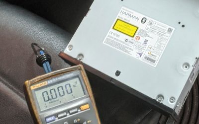
The multimeter is a great option to accurately measure the power and ground circuits when using an adapter like the Load Proâ„¢ to measure a perceived voltage drop at either B plus or B minus. Voltage drop also means the entire circuit through all connections and includes control relays. Keep it simple.
The image below is reading the current draw with an amp clamp attached. At the mV scale, the parasitic draw is 4.2 amps. In this case, the CAN network would not enter sleep mode with the ABS warnings/messages for skid control.
Use the oscilloscope to recognize the different signatures (voltage over time). It offers a much more pronounced view of how the device is intended to work or is having a “very bad day.†The modern oscilloscope can accept peripherals such as amp clamps, temperature probes/sensors, pressure transducers, fiber optics, etc.
Not all oscilloscopes are equal. Some can operate within different time bases, multiple channels and have built in attenuation. Others have some very interesting functions and software that will put your doctor’s equipment to shame.
The compression image was created with a digital oscilloscope and an analog pressure transducer.
Note: With a schematic and a dependable multimeter, test/record the device or harness measurements. When measuring with an oscilloscope, set up accordingly or expect damage/erroneous readings.
Hint: The operation of a device or component is as good as the controller software that operates the device or component.
Think about this! A multimeter can be used to measure a CAN system. There will be agreement on measuring the internal resistance of a node or network total resistance of the measured network. Realize that many models will have more than one network.
A resistance test may tell one story of connectivity between nodes. More importantly, what will the messages look like when the network is operating and sharing data between the active nodes?
The image has been captured at the ABS controller. This network is interconnected to the ECM, TCM, Airbag and Instruments. No matter where the connection is made, the messages are identical when shared within this network.
The only changes that can be recorded are the messages shared between the nodes. This image is correct and of a no fault network.
What does a scan tool display with a VW with a 2.0L automatic? This following set of digital data is measured values at the ECM:
- Group 125 Field 1 – Transmission 1
- Group 125 Field 2 – ABS 1
- Group 125 Field 3 – Instruments 1
- Group 126 Field 3 – Airbag 1
The digit 1 = OK and the digit 0 = not OK after the
named controller.
This network with the digit 1 following is an intact and communicating network. If one or more controllers show the digit 0, then that specific network is non-communicating. If one or more networks toggles from 0 to 1 and switches, obviously one or more nodes is having “a bad day.â€
What will the ABS data look like when measuring the ABS network connection?
| Group 125 Field 1 – Engine 1 |
| Group 125 Field 4 – Transmission 1 |
How about the TCM, is there a relationship?
| Group 125 Field 1 – Engine 1 |
| Group 125 Field 2 – ABS 1 |
| Group 125 Field 3 – Instruments 1 |
What is the Airbag controller connected to?
| Group 125 Field 1 – Instruments 1 |
Lastly is the Instruments controller (gateway).
| Group 125 Field 1 – Engine 1 |
| Group 125 Field 2 – Transmission 1 |
| Group 125 Field 3 – ABS 1 |
| Group 126 Field 1 – Steer. ang. 1 |
| Group 126 Field 2 – Airbag 1 |
| Group 127 Field 2 – AWD 1 |
Groups 130 to 140 are the relationship between the Comfort Control System and Central Electronics.
In the digital world 1 or 0 is the difference between active and not active. If the controller was never built into the vehicle, the measured value indicates a zero.
Interesting “digital screwdriver?†Here is a VW Tiptronic gate that actually worked. Attached is a magnetic screwdriver accessing the “digital sensors.â€
Three sensors, three messages proving the used Tiptronic circuit board works.
The discussion has nothing to do with retiring the multimeter. Today’s technician has been using the modern multimeter for quite some time with modern technology offering quality attachments to enhance multimeters. Even with the addition of temperature sensors such as “K†type or infra-red attachments, amp clamps, pressure transducers, and electrical load test leads, the meter still has a distinct place within a diagnostic session.
The disadvantage is when a component can not be tested or can be quite difficult to test because of how the module, device, or assembly is manufactured. There will be instances where the multimeter can not be used to measure an internal temperature sensor, an internal speed sensor, or an inaccessible micro switch. How about a Bluetooth module incorporated within the entertainment system? If any test can be accomplished, that test may be powers and grounds or view the digital data transfer with an oscilloscope.
The modern scan tools will have access to the systems and realize that these systems will have an interrelationship. The example of the Bluetooth system will certainly incorporate the entertainment system, sound system and, likely, the steering wheel pad with the steering wheel electronics control module.
We’re dealing with a network on wheels. Much more on digital data later.
Download PDF


0 Comments