Some have clutches, some don’t. Some are the scroll type, some aren’t. How do you know if they’re doing what they’re supposed to do?
An air conditioning compressor does two things that its name implies. First, it’s responsible for “conditioning†the air in the vehicle’s cabin. It not only cools it down, but also reduces the moisture content, or humidity. Second, it compresses refrigerant vapor to high pressure and sends it to the condenser. All air conditioners work the same way whether they are installed in a building, or in a car. The refrigerator or freezer is an air conditioner as well.
The heart and soul
The basic principles of automotive air conditioning systems have not changed much in recent years, but the compressor sure has. The workhorse of the air conditioning system, the compressor is powered by a drive belt connected to the crankshaft of the engine, or in more modern engines and especially hybrids and electrics, driven by an electric motor. Any compressor draws in low-pressure refrigerant vapor to start the refrigeration cycle. Much like the human heart that pumps blood through the circulatory system, the compressor pumps the air conditioner’s life blood (refrigerant) through the system.
Thermodynamic review
As mentioned, A/C system principles have not evolved as much as compressors have. Let’s take a quick review of all the components in a modern system and how they cooperate with the compressor.
The condenser is used to change the high-pressure refrigerant vapor into a liquid. It is mounted in front of the engine’s radiator, and it looks very similar to a radiator. The vapor is condensed to a liquid because of the high pressure that is driving it in, and this generates a great deal of heat. The heat is then removed from the condenser by air flowing over it. Most Mercedes-Benz vehicles you service will have additional electric cooling fans to aid in this process. This is essential to the longevity of the compressor.
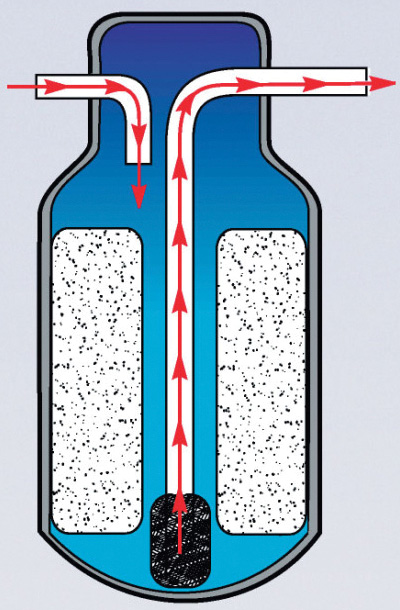
After the condenser, the now-liquid refrigerant moves to the receiver dryer. This is a small reservoir vessel for the liquid refrigerant, and removes moisture that may have infiltrated the refrigerant. Moisture in the system wreaks havoc, with ice crystals causing blockages and mechanical damage.
The pressurized refrigerant flows from the receiver drier to the expansion valve or block. This removes pressure from the liquid refrigerant so that it now expands and becomes a vapor in the evaporator. This change-of-state is what absorbs the heat inside the cabin.
The evaporator is located in the interior of the vehicle in the HVAC ducting system. As mentioned, the cold low-pressure refrigerant passes into the evaporator vaporizing and absorbing heat from the air in the passenger compartment. The blower pushes air through the evaporator thus circulating “coolness†inside the car. The moisture in the air is reduced, and the condensate is collected and drained away via the evaporator drain tube.
There’s always been a need for cooling
According to some documents we’ve read, experiments in air conditioning through the 1930s included liquid nitrogen, a “vapor jet†system that used a water-alcohol mixture, an “air cycle†system that used a turbine-powered compressor and a gasoline vaporization system that required 26 gallons of gas an hour!
In the 1930s, according to Americans on Vacation, drivers in southwestern states could rent a “hang-on†air conditioner that contained cold water or ice in a cylinder that attached to the car window. It cooled the interior when air blew through it. In the early days of air conditioning an ice-block experiment was run to see how effective cooling could happen. Blocks of ice were placed in the back seat to see how much energy would be required to cool a car. With the back seats removed and a hole drilled into the floor for drainage, the engineers would drive for a while, then stop and weigh the ice, to determine how fast the ice was melting. Their conclusion:
“With the ambient temperature at 95 degrees in bright sunshine, with 40 percent relative humidity and the windshield open half an inch (windshields opened in those days), it required heat removal at 12,000 BTUs per hour to maintain an interior temperature of 85 degrees, at 65 mph.†The objective was to bring the temperature down by only 10 degrees they concluded because in the early 1930s it was believed that if the temperature was cooled much in excess of 10 degrees it might cause a person to faint from shock when emerging from the air-conditioned space. With the change in these antiquated ideas, the need for air conditioning systems and as we shall see compressors, needed to evolve and change.
Reciprocating piston compressors
The York-Tecumseh style compressor was an early design, which was standard equipment on many Mercedes-Benz vehicles from 1959 to 1979. While a rarity these days, it can be identified by its large square shape reminiscent of a lawn mower engine, being a reciprocating piston pump. The reciprocating motion causes it to vibrate more than modern Sanden compressors. It also had higher torque requirements for peak pumping, and it doesn’t like high rpm operating speeds.
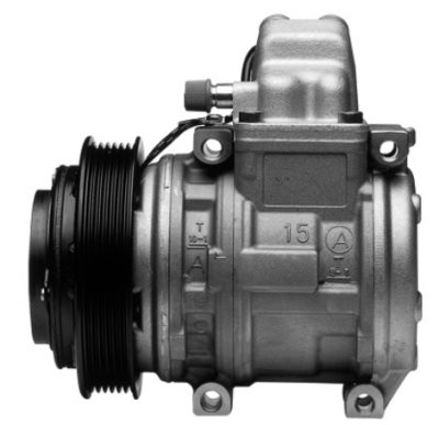
There are two types of piston compressors currently in use, the opposed axial variety (also often referred to as the swash plate type), and the single-row axial or wobble-plate type. These may contain five, six, seven, or ten pistons around their diameter, thus the term “axial.†They’re easy to spot with their barrel shape, aluminum color, and small overall size. Even though they are commonly referred to as rotary, they’re really not.
With either type of piston compressor, the pumping action of the pistons draws low-pressure, low-temperature refrigerant vapor from the evaporator in through suction valves. The refrigerant exits the compressor through discharge valves as a high pressure/high temperature vapor. This happens because the pistons are pumping the refrigerant against a calibrated restriction in the system. Depending on the type of system, the calibrated restriction is contained in either the orifice tube or the expansion valve.
Each cylinder in the compressor contains one suction and one discharge flapper-type reed valve. As the piston moves away from the suction valve, the valve opens and refrigerant is drawn into the cylinder. After reversing direction, the piston compresses the low-pressure, low-temperature vapor into a high-pressure, high-temperature vapor. This exits through the discharge valve on its way to the condenser.
Also included in this category is the scroll-type compressor, well known for its low noise and high performance. The compressor chamber consists of a pair of spiral-shaped scrolls; one fixed and one rotating. Although the idea of a scroll compressor is not new, actual production versions are a relatively recent technology. The first scroll compressor patent dates back to 1905 and Léon Creux, a French engineer, but it was not until the early 1970s that precision machining technology made a working prototype possible.
Rotary
These include Electrical (ES) Compressors also known as the Electrical driven Scroll compressor. It has a variable displacement and is hermetically closed reducing leakage of refrigerant. This compressor also has the capability of A/C operation also when the engine is switched off. The Compressor chamber consists of a pair of spiral-shaped scrolls; one fixed and one rotating. Another type of rotary compressor is the Through Vane (TV) Compressor. It is A rotating type compressor with a Compressor chamber consisting of a rotor with two vanes sliding through the rotor. Two different displacements are available from Nippondenso, 120 cc and 140 cc.
Clutchless compressors?
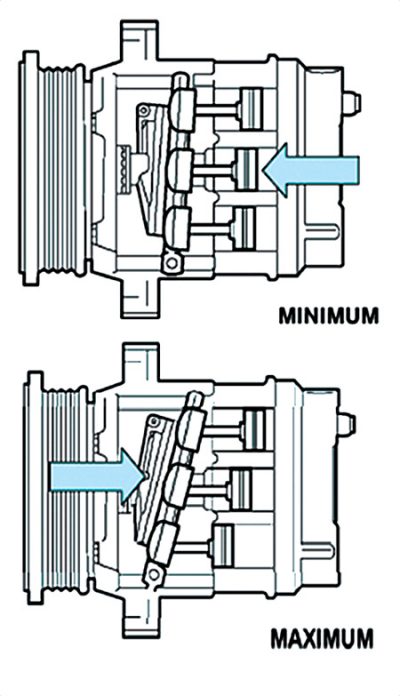
When the air conditioner is turned on, a sudden large power drain occurs both in the torque required to spin the compressor, and the amperage required to engage the clutch. This can be mitigated by keeping the compressor engaged all the time and varying its displacement according to demand, hence its load. It also spares the moving parts the shock of going from zero to thousands of rpm instantaneously.
The variable-displacement compressor is an axial design with the pistons driven by a wobble plate or a swash plate. Since the angle of that plate determines the length of the stroke, changing that angle varies the distance the piston moves, thereby regulating the amount of refrigerant pumped (displaced). The plate angle is controlled by means of linkage and springs, and it’s adjusted by changing refrigerant pressure in the compressor housing.
When housing pressure is increased, it pushes on the back side of the pistons keeping them “higher†in their bores, closer to the cylinder head. This reduces the angle of the swash plate and shortens the stroke, decreasing displacement. When housing pressure decreases, a spring pushes the adjusting linkage away from the cylinder head, increasing plate angle and lengthening the piston stroke for more displacement. Housing pressure is controlled by a valve with ports and passages that connect to the suction (low-side) and discharge (high-side) chambers of the compressor head.
Trouble shooting
There are different means of determining the efficiency of each type of compressor and model. It’s vitally important that you consult the service manual for the specifications and characteristics of the vehicle you are working on. The basic approach to diagnosis, however, remains pretty much the same. The major differences will be in whether or not you’re dealing with a variable displacement clutchless compressor, or one of the more conventional pumps.
If you have a complaint of a low or no cooling on a clutched system, there are important service bulletins available from Mercedes-Benz. Start with the basics. Is the clutch engaging? If not, is the PCM commanding it on? The following steps from SDS will help with your diagnosis.
Prerequisites:
- Before parts can be replaced, the exact quantity of the refrigerant in the system must be determined by evacuating the system.
- If the fill level of the refrigerant circuit is too low, parts should only be replaced if the torque limiter is broken.
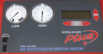
- If the fill level of the refrigerant circuit is too low and the torque limiter is damaged, the leak test (Test 6 “Leak in refrigeration circuitâ€) must be performed first using the “Technology Guide –Vehicle Climate Control†located in SDS SD Media, then the system must be refilled and checked. If the amount of refrigerant is less than 80% of the proper charge, it’s too low, which may be the cause of the air conditioning shutting down or malfunctioning. Most high-quality AC recovery/recharging machines will do a leak test after evacuation. Any detectable, measurable leak is unacceptable, so a repair will be necessary.
Remedy A – Broken Torque Limiter:
- Ensure the alternator freewheel (when applicable) is not damaged and that the belt pulley of the compressor rotates in the belt drive.
- If the alternator freewheel is blocked, replace it. Some compressors have a replaceable belt pulley, but with others a new compressor is required. Refer to your authorized Mercedes-Benz parts distributor using the applicable part number.
- If the alternator freewheel is not blocked and black refrigerant/oil is evacuated from the system, replace the AC compressor.
Remedy B – Blockage in the Refrigeration Circuit
- Identify through SDS function test “Refrigeration circuit test†that the refrigerant circuit has not been underfilled or overfilled.
- Inspect along the AC lines to check for blockage at the points with marked temperature differences. A thermal imager is handy in this case.
- Identify and replace the blocked components in the refrigeration circuit.
Remedy C – Electrical Fault in Refrigerant Compressor
- Identify through SDS function test “Refrigeration circuit test†that the refrigerant circuit has not been underfilled or overfilled.
- After ruling out a short circuit in the actuation and ground wiring, replace the refrigerant compressor only.
Note:
- Always empty the oil from the new compressor before installing.
- Refill the compressor with the proper oil, ensuring that the quantity is correct (refer to WIS document BF83.00-Z-9999AZ). Take into consideration whether an individual component or multiple components are to be replaced.
- Always perform a leak test on the system after any repairs to the refrigerant circuit, but before filling it with refrigerant.
You can’t go by pressures alone
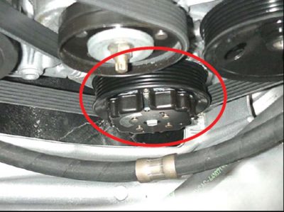
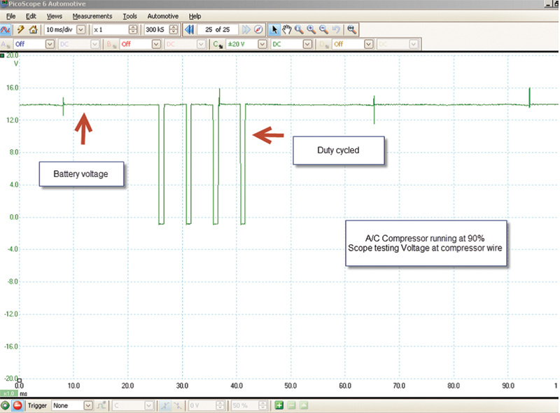
The control unit uses a PWM (Pulse Width Modulated) signal to the compressor control solenoid to vary the output level of the compressor. The ability of the control unit to consider evaporator temperature, engine rpm, high-side pressure, accelerator pedal position, and ambient temperature when deciding to increase or decrease refrigerant flow from the compressor makes this system completely interactive. When seen on a running engine, a clutchless compressor gives the appearance of a regular clutch-type unit with the clutch engaged because the front hub plate is always spinning. The clutchless compressor will reduce the swash plate angle to 2% when the system is not activated by the control unit, producing nearly equal suction and discharge pressures. With the compressor shaft turning and pressures almost equal, many technicians assume the compressor is defective and will mistakenly want to replace it. You’ll have to go into your scan tool and watch the PIDs for the control solenoid to see whether or not the problem is in the compressor or the electronics.
The Future is Here
Mercedes-Benz will be the first carmaker to equip production models with CO2 air conditioning systems. CO2 systems are said to perform better than conventional systems and to be more environmentally friendly. The move is in response to an EU directive that went into effect in 2017. The legislation is based on the EU’s climate protection requirements and Mercedes-Benz has been involved in drafting the standards for the use of the new technology. It says the standards will help other carmakers to begin development of their own systems quickly.
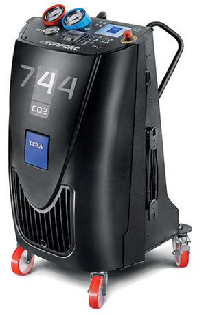
CO2 systems operate at a pressure 10 times higher than today’s typical R134a refrigerant systems, at more than 100 Bar! As such, the new systems require designs and components that can handle the increased pressure safely. To sustain and contain a required pressure on the order of 1,500 psi, Mercedes-Benz had to redesign everything — all-new compressors, hoses, seals, you name it.
The new R744 compressor has a 31cc capacity, a fifth of the PX R134a unit it replaces, but manufacturer (and Mercedes-Benz supplier) Sanden claims its “cooling performance and function exceeds conventional compressors.†Its packaging and weight is also said to match that of the PX R134a compressor, and it’s able to withstand the tremendous operating pressure. Sanden also says the R744 pump includes internal design features for reduced noise, and new control technology that improves its stability and safety.
Mercedes-Benz will be the first to both award development contracts and place production orders for CO2 air-con systems and their components. The new technology will debut on European S- and E-Class models.





0 Comments