
Did you ever wonder how things can get so out of hand?
Hint 1
Never assume and keep it simple.
History
An acquaintance asked for some technical help with this model Audi that experienced a no crank/no start. The comedy was sending a camera image of the Autologic screen with the ECM fault via email.
Reality
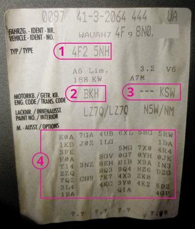
The correct method is to send/save the entire autoscan with the PR tag found in the trunk or within the owner’s maintenance manual.
The autoscan was accessed and saved when arriving at the facility. It was quite interesting and lengthy as well.
ECM |
| 012371 – Starter Control; Returned Message |
| P3053 – 006 – 50 Short to GrounD |
| 012424 – Starter Relay |
| P3088 – 006 – Electrical Malfunction |
| 012403 – Fuel Pump Circuit |
| P3073 – 007 – Electrical Malfunction |
ABS |
| 01826 – Sensor for Steering Angle |
| (G85); Supply Voltage Terminal 30 |
| 00532 – Supply Voltage B+ |
| 002 – Lower Limit Exceeded – Intermittent |
Acc/Start Auth. |
| 00532 – Supply Voltage B+ |
| 002 – Lower Limit Exceeded – Intermittent |
| 00446 – Function Limitation due to Under-Voltage |
| 002 – Lower Limit Exceeded – Intermittent |
Control Head |
| 01964 – Control Module for Seat & Steering Column Memory (J136) |
| 004 – No Signal/Communication – Intermittent |
Cent. Elect. |
| 02382 – Sensor for Light Detection (G399) |
| 014 – Defective – Intermittent |
| 00924 – Relay for Headlamp Cleaning System (J39) |
| 014 – Defective – Intermittent |
Airbag |
| 00532 – Supply Voltage B+ |
| 002 – Lower Limit Exceeded – Intermittent |
| 02095 – Component Protection Active |
| 000 – Intermittent |
Steering wheel |
| 00446 – Function Limitation due to Under-Voltage |
| 002 – Lower Limit Exceeded – Intermittent |
| 00532 – Supply Voltage B+ |
| 002 – Lower Limit Exceeded – Intermittent |
Navigation |
| 00446 – Function Limitation due to Under-Voltage |
| 002 – Lower Limit Exceeded – Intermittent |
Headlight Range |
| 00446 – Function Limitation due to Under-Voltage |
| 002 – Lower Limit Exceeded – Intermittent |
Central Conv. |
| 01134 – Alarm Horn (H12) |
| 012 – Electrical Fault in Circuit |
Centr. Electr. II |
| 00532 – Supply Voltage B+ |
| 002 – Lower Limit Exceeded – Intermittent |
| 00446 – Function Limitation due to Under-Voltage |
| 002 – Lower Limit Exceeded – Intermittent |
| XXX |
Battery Regul. |
| 02277 – Quiescent Current Stage 6 |
| 02272 – Quiescent Current Stage 1 |
| 02273 – Quiescent Current Stage 2 |
| 02276 – Quiescent Current Stage 5 |
| 02274 – Quiescent Current Stage 3 |
Tire Pressure |
| 00532 – Supply Voltage B+ |
| 002 – Lower Limit Exceeded – Intermittent – MIL ON |
| 01521 – Sensor for Tire Pressure |
There are 30 main controllers (CAN) attached to this Audi with various sub-modules that are also attached to a LIN (Local Interconnect Network) and MOST. The remaining controllers not listed had no faults recorded.
Hint 2
Autoscan the vehicle again after any repair or part replacement.
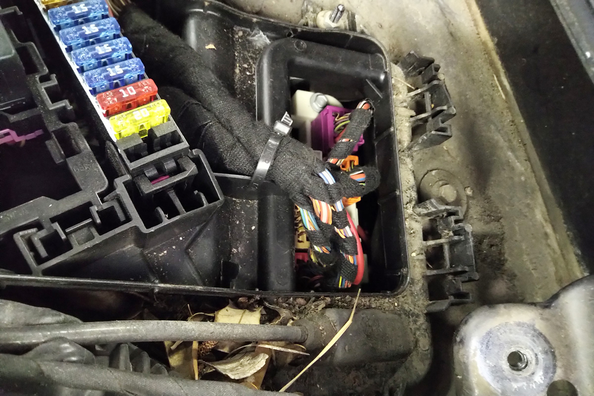
The shop that was attempting the repair took it upon themselves to replace the relays that may have been in question for “Start Authorization.†Those relays were situated under the driver side dash and mounted at the firewall.
In this case, the relay assembly was easy to access, monitor and measure.
Noticed during the analysis and inspection of the A6 was the inner plenum area where leaves, twigs, seeds, and debris of all types accumulated and we wondered how long and how much moisture may have accumulated over time. That being said, how many rodents had a party in that area?
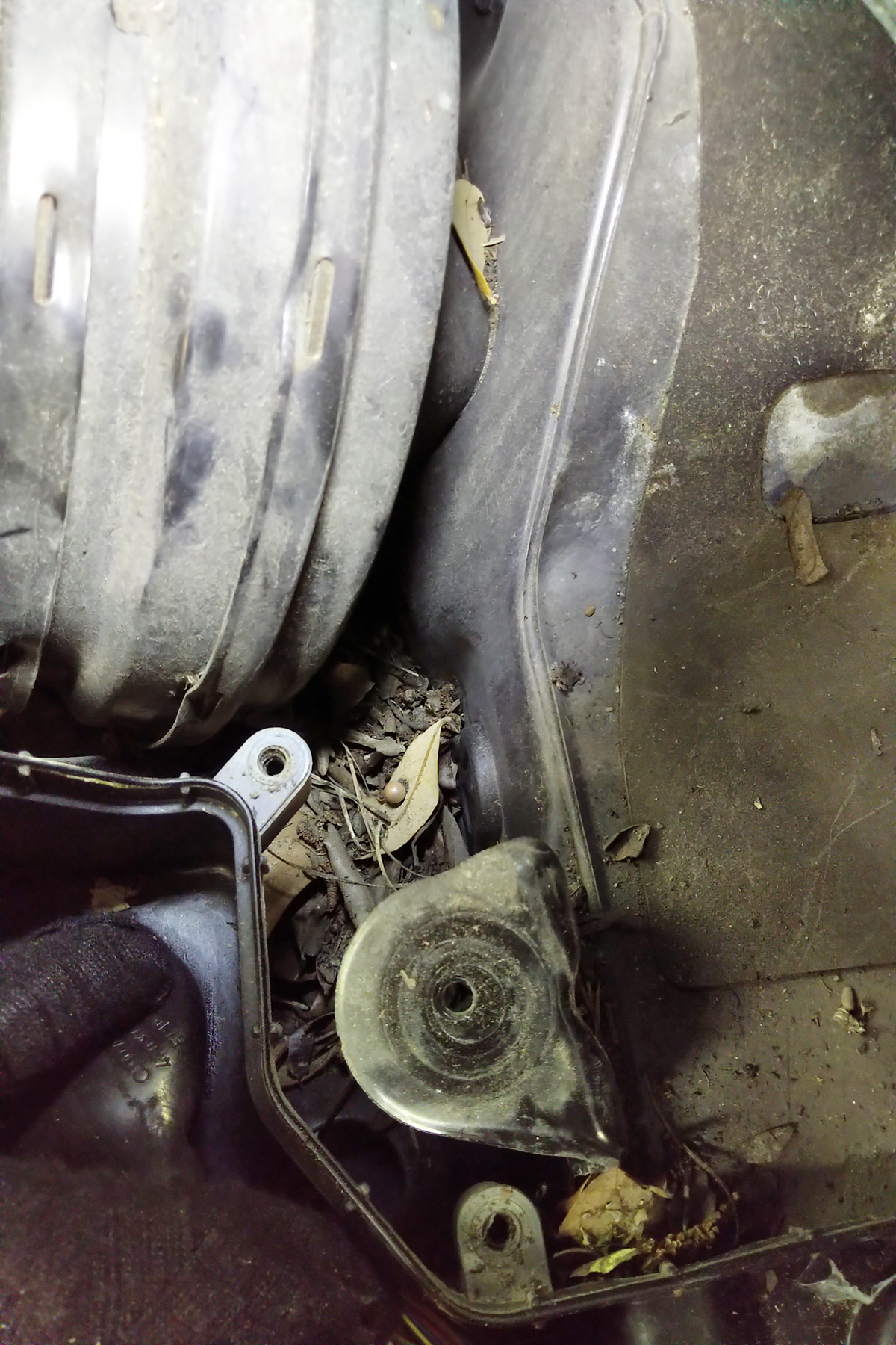
Side note: Cleaning the plenum and replacing/checking the dust and pollen filter should always be part of bi-yearly maintenance.
Imagine the removal of the wiper assembly and the effort to clean the area.
With the area cleaned and inspected, there were no signs of water or rodent intrusion. The best option is to ensure a clean and stable power supply at the battery (test it as well with a carbon pile). With a captured and saved primary autoscan, delete all the faults and save the latest recording with one or two key cycles. The majority of the B+ or Battery Supply faults did not return except for the repeated ECM, ABS, and Central Convenience faults.
Where to start
Why not eliminate the starter first? A high quality momentary push button attached to the solenoid proves the starter rotates. Additionally, remove the Starter Relay (Position 4) and apply B+ to Pin 8 (BLK/RED).
High quality schematics fitting the A6 can be found in erWin (only a personal choice) but many on-line subscriptions offer schematics that can be printed, cut, and taped together. Get your markers ready, attach the schematics to a board and note each step.
Quality relay breakout kits are available and do work well but, in this case, the entire relay station can be rotated (inverted/rotated) and back probed.
Back probing can also mean closing the relay with a ground connection or monitoring the B+ and controlled power supply. Monitoring can also mean the relay is being closed by the security system or control unit. Remember to use perfect fitting male PINs to simulate a relay leg.
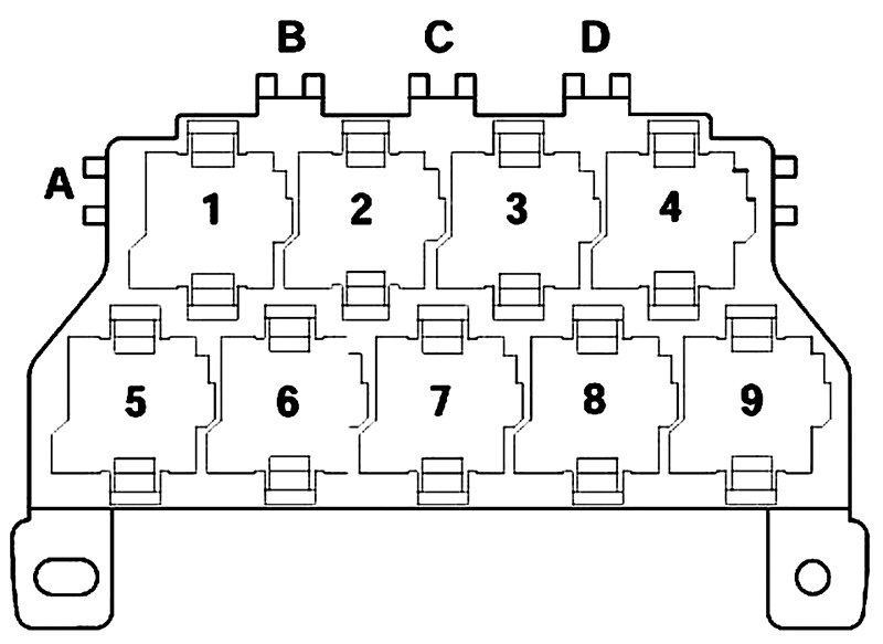
There are three relays on this model that required testing (1, 4 and 6). Since the Audi woke up and was scanned, Power Supply Relay J329 now works.
Hint 3
NEVER operate a power probe to activate or ground any computer controlled relay. Expect damaged internal components with the “but it ran before it came in the shop†expression.
For the sake of simplicity and if there’s a desire to learn to read schematic diagrams, apply and prove this no start condition, then follow this style of thinking.
- At the following link, the identical schematics have been provided.
- Download and print all schematics. Keep the sets separated. They are named in the subsequent order:
- Access start 1, Access start 2
- Alarm 1, Alarm 2
- Engine 1, Engine 2, Engine 3, Engine 4
- Starting
- Trim the sets such as Access start 1 and Access start 2 so they fit together and attach the two schematics together with tape.
- Beg borrow or steal some crayons or colored markers (red, blue & green).
- Follow the instructions for Access start 1 and Access start 2.
- Access/Start Authorization (Access 1 and 2)
- Power Supply Relay (Terminal 15)
- With red marker
- Pin 2 (BLK) to Pin 18 Access/Start Control Module with (BLK) at Power Distribution System
- Starter Relay and Starter Relay 2
- With red marker
- Power Distribution Pins 4, 8, 2 all (BLK) With blue marker
- Both relays, Pins 6 (BLK/BLU)
- Follow the instructions for Alarm 1 and Alarm 2 (Alarm Horn).
- With red marker
- Pin 3 (RED/GRN changing to RED/GRAY) of alarm horn to Fuse 7 (5A)
- With green marker
- Pin 2 (BRN) to ground connection
- With blue marker
- Pin 1 (BLK/YEL) to Pin 18 Comfort Control System
- Follow the instructions for Engine 1 through 4.
- With red marker
- Pin 32 (BLK/RED) Starting/Charging System
- With blue marker
- Pin 46 (BLK/WHT) Starting/Charging System and Pin 23 (BLK/BLU)
- Follow the instructions for Starting.
- With red marker
- For both Starter Relay and Starter Relay 2
- Pins 8, 4 and 2
- At Starter Relay Pin 8 (BLK/RED) to Starter Pin 50 also connecting to ECM Pin 32
- With blue marker
- Pin 6 at Starter Relay to Pin 46 of ECM
- Pin 6 at Starter Relay 2 to Pin 23 of ECM
View the colored pages now and notice the interrelationship between the control modules, starter and relays for this model.
In simple terms
The ECM controls the relays in the proper order if authorized by the Start/Access Control Module.
The Start/Access Control Module and the ECM MUST recognize the ignition key(s).
The ECM controls the Starter Relay and Starter Relay 2 by enabling an internal ground circuit via Start/Access Control Module. Access is determined via CAN between these two controllers if the key(s) and associated controllers match.
If the B+ connections are stable from the Power Distribution System and the voltage drop is within reason, then determine what closes the relay(s).
Quality jumper wires were used to “ground†the control (Pin 6) of Starter Relay 2 and the current flow was measured towards the Starter Relay (Pin 2). If the Starter Relay Pin 6 was grounded then the starter should rotate.
That is all true but…
The problem is still a no crank/no start with the ignition key(s). The next step will certainly create faults within multiple controllers and knowing that fact, we disconnected the battery and disconnected the ECM.
After re-connecting the power supply and ensuring both relays had a power source at Pins 2 and 4, the next step was to ground Pins 46 and 23 at the ECM. If the colored schematics were followed exactly, then the grounding of both ECM pins proves that both relays operate correctly and the two wires at the ECM are intact.
Disconnect the battery again, ensure the ECM connections are clean and re-connect both the ECM and battery. Scan once again and clear ALL faults with at least one ignition key cycle.
Is there something missing?
Yes there was, and we noticed what a co-worker had said, “Did you hear that? Did you feel that?†The car did start and ran quite well at that moment.
After testing clearing/all faults and re-setting the ECM and ABS adaptations, there were two more faults in one controller remaining…
Central Conv. |
| 01134 – Alarm Horn (H12) |
| 012 – Electrical Fault in Circuit |
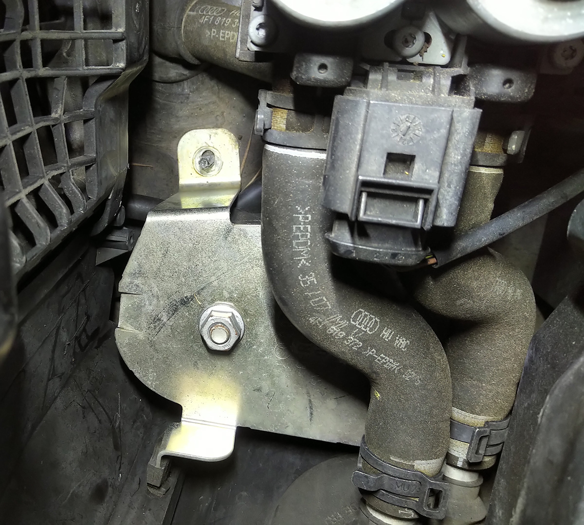
Remember the debris, the leaves, seeds, twigs etc. etc. etc.?
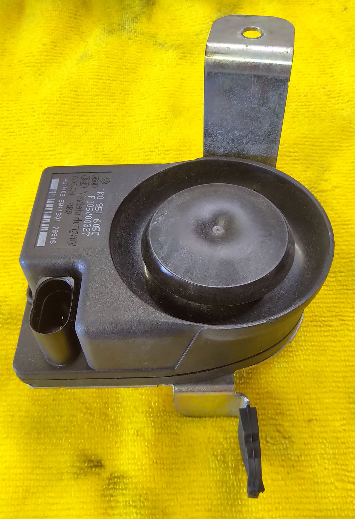
One would wonder with this module sitting at the bottom of the plenum and absorbing the “compost.â€
This brings us back to the old Volvo days when that type of module was bolted and riveted under the right front fender and that “tow in with no start†condition.
Fortunately for the customer, the local dealer found and ordered the new module for the next day. Of course the replacement had an updated part number and once it was installed, no faults returned. The last scan returned as perfectly clear.
Will the A6 start without the module?
Yes it will.
Was this exercise pointless?
Not really, we all acquired great cutting, taping and coloring skills.
How and why did this module fail to the point of a no start?
Unfortunately the customer wanted the module and couldn’t “open†it but, very confident when it was installed again, the same fault returned.
The replacement was definitely the cure.
But what about the original module?
Once again, follow this path with this download. The text document provides very good links and images to repeated problems. The images and links appear to be identical part numbers but in different models.
Remember the story about the Volvo? Same problem, same battery deterioration on the circuit board, same no start. Welcome to the future.
Side note
Don’t waste your time attempting some of what those links profess as a cure, repair or adaptation. The damage has been done and that part about the “guarantee†is no different than winning a lottery.
With the new module installed and no faults recorded, the Audi was returned to the customer.
Explanation and operation “If – Then – Elseâ€
If for any reason the Alarm Module has a fault and is possibly active on the network, then expect the engine not to start with multiple faults.
What about this one controller that recorded “Battery Management Faults?â€
Battery Regul. |
| 02277 – Quiescent Current Stage 6 |
| 02272 – Quiescent Current Stage 1 |
| 02273 – Quiescent Current Stage 2 |
| 02276 – Quiescent Current Stage 5 |
| 02274 – Quiescent Current Stage 3 |
Stage Meanings:
Stage 1. CAN Convenience loads are deactivated.
Stage 2. Additional CAN Convenience load with Infotainment System restrictions.
Stage 3. Initialization of KEY ON “closed circuit†current reduction.
Stage 4. Deactivation in this stage can only be performed by a VAG style scan tool. The J644 module can not independently initiate this program.
Stage 5. Deactivation of the auxiliary heater.
Stage 6. Reduction of Bus system wake-up.
As with all schematics, take them with a grain of salt and recognize that Central Convenience Controller and the alarm horn gave out one piece of information within the scan as to how they interconnect:
- Subsystem 1 – Part No: 1K0 951 605 C
- Component: LIN BACKUP HORN H03 1301
Some Audi models have an Interior Monitoring System with a parallel connection to the LIN BACKUP HORN output to Central Convenience.
Now imagine a LIN controlled alarm that has a backup battery and damaged circuit board screaming and yelling in silence and considered a parasitic load.


0 Comments