How they work, wake-up signals, testing and repairs
Fiber optics are generally relegated to the infotainment systems of Mercedes-Benz vehicles, including the sound system, navigation screens, backup cameras, etc. But first things first: Why fiber optics? The short answer is simplicity. Vast amounts of information needs to be sent in the case of body and comfort systems. This would require extremely complex wiring which can be reduced by using a fiber optic network. Just as a fiber optic internet service provides superior information transfer in a single fiber optic cable to your home, fiber optics provides that in spades in Mercedes-Benz comfort systems. In the case of the MOST fiber optic network, the data rate of 24.8 Megabits-per-second (initially; subsequent generations increased this to about 150 Mb/s today) is significantly faster than the D2B predecessor at about 5.6 Mb/s. A secondary benefit of fiber optics is they are nonmagnetic so they are not subject to RFI (radio frequency interference). Also corrosion, water damage and intrusion are non-issues.
Fiber optics used by Mercedes-Benz are plastic fibers that pass light signals from one component to another. Each component has two fiber optic cables, an in and an out. These light signals get converted to electrical signals and the components either use the information to either operate or pass it further along to the next component.
The first version of fiber optics developed by Mercedes-Benz was introduced in Model Year 1998. This fiber optic system was called Domestic Digital Bus (D2B), which was later upgraded to Media Oriented System Transport (MOST) bus starting around 2003 with the introduction of the E-Class type 211. Though both operate the same way, the MOST systems are faster and tougher. In general, the minimum bend radius of a fiber optic cable is 25mm (about an inch), but in any case they must not be kinked or cut.
In contrast to the D2B system, MOST is an industry-wide system with somewhat lower costs and greatly increased capacity, capable of up to 64 devices on a network. Components using MOST get all their information optically, so they only need three wires (power, ground, and wakeup) and, of course, the two optical fibers (in and out).
D2B
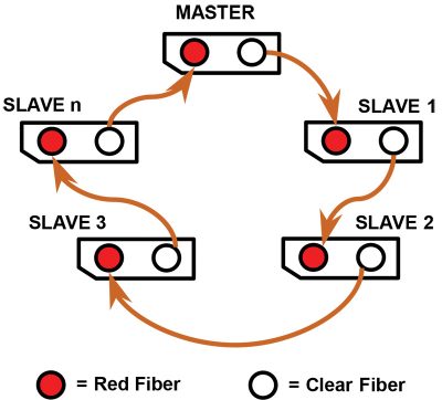
As mentioned above, Mercedes-Benz began its foray into the world of fiber-optics with the D2B (Domestic Digital Bus) system, which was developed exclusively by the company. This is a series routed network, meaning there is one fiber-optic cable coming in and another coming out at each component, and so on down the line in a daisy chain type of loop. D2B fibers are identified by their dark orange insulation. Light enters the clear part of the connector and exits the red portion. Don’t touch the exposed fiber ends!
The system has a master controller that is in command of all the other components in the network. When communicating with the network using your Star Diagnosis or XENTRY system, this is the control unit you are communicating with. In the coding of the master control unit, it needs to know both the order and type of components in the system. Not all are the same, since vehicles may have different options installed. If one component in a system in series goes down, then the entire network goes down.
Configuring the D2B Ring
Configuring the components in the D2B system is of utmost importance. Here is an explanation of how engineers have ordered the system to be set up. It should be noted that the MOST configuration is quite similar.
1. Vehicles delivered from the factory may have active fibers (e.g. sound amplifier and/or factory installed CD), inactive fibers (e.g. no amplifier or accessories installed), or no fibers (sometimes seen in non-US vehicles). Vehicles will vary in accordance with installed equipment. Some vehicles will have all required fibers installed while others will contain additional fiber cables in the kit for installing a new accessory. Refer to the respective accessory reference or installation instructions for fiber location information.
2. To remove/install components (for example a CD changer) the D2B ring must be “broken†and the appropriate adjustments made to the configuration. Components will have either a straight or 90 degree angle connector (depending on location and available space), and cables are generally unbroken but can have up to one in-line splice connector installed.
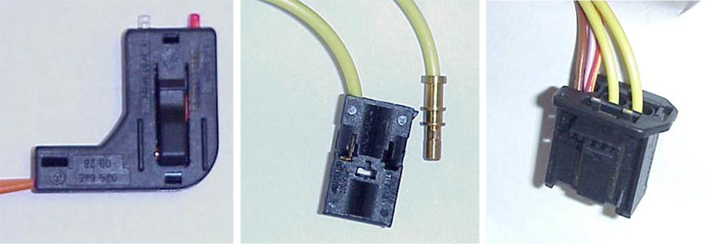
3. Exercise extreme care when disassembling connectors and handling fibers to ensure no fiber ends are damaged and cables are not kinked. Fiber damage will result in light loss that could lead to intermittent D2B ring operation and/or failure, thus needing replacement.
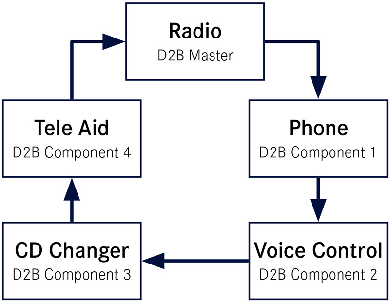
4. The D2B ring configuration varies according to vehicle type and in accordance with the vehicle’s equipment level. Check the near-by figure to see an example of a configuration. Consult the vehicle data card and WIS to find the correct “as built†configuration of a specific vehicle. Some installations will not include all the components shown in the examples. If a component is not present, connect the preceding component output to the input of the one following the component not present. Once again your SDS or XENTRY should be able to show you the components you already have in the system
5. Do not leave any blank or “Not Present†between components when setting the configuration. All components must be listed one after the other in proper order, and then after the last component, the remaining entries should be set to “Not Present.â€
6. Only vehicles with COMAND or MCS include the Tele Aid module in the D2B ring.
7. Confirm the programmed and actual configurations match once the ring is properly version coded. This can be accomplished by using the D2B actual values function. The paths to access this feature may vary depending on the test equipment and software level, but in general you go to Actual Values for the Master component (generally the head unit) and check the menu item D2B Actual Configuration.
8. Verify the version coding input (specified value) matches the actual configuration performed during installation (actual values). If a difference exists, the ring has been improperly configured and must be disassembled and corrected.
| CAUTION |
|---|
| Do not alter the configurations in the diagrams to match the vehicle configuration; instead always change the vehicle to match the diagram. Failure to have the configuration set as illustrated in the workshop manual will result in erroneous system operation and/or intermittent failure of some or all components as well as failure of the diagnostic system to provide accurate diagnostic messages. |
While it would be unusual for the vehicle’s physical configuration to change, particularly in an older model, don’t discount this as a possibility: Ask the customer if any recent work was done to the vehicle, such as a collision repair. Untrained hands might not understand that a fiber optic connection shouldn’t go just anywhere it’ll fit.
9. Check the DTC memory of all installed components and the head unit. Any present DTC(s) should be diagnosed, identified, corrected and the DTC memory cleared.
| NOTE |
|---|
| Powering up a newly installed system prior to version coding will set D2B ring configuration errors. These errors may be ignored during the initial DTC check. If, after clearing the DTC(s), they return in subsequent operation of the system, a configuration error is present that must be located and corrected. |
10. Perform a short functional test on the D2B system group and confirm every system works properly and that no new DTC(s) have been set.
MOST
In a MOST system, the master controller issues an optical and an electrical “wake-up†signal to all components in the system simultaneously, and also records or flags diagnostic trouble codes (DTCs) that provide the location of the electrical or optical fault. Just as with D2B, each component has an “in†optical cable and an “out†optical cable.
In MOST systems, the in cable will have an arrow on the connector pointing toward the component, and flashing red light will be emitted. The out cable will have no light when unplugged from the component (but light may be emitted from the component), and an arrow pointing away from the component. The out cable will pass along the light to the next component once the connector is plugged back in. As with D2B, MOST is configured in series as a loop, and the information is transmitted in only one direction, meaning that the light pulses for the voice control system control unit (for example) also run through all the other components connected to the MOST ring.
Wake Up!
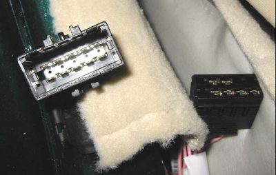
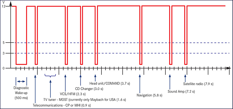
No you’re not late for work, but one of the components in the MOST system might be, or perhaps a no show. The MOST master issues an electrical wake-up signal to each component and, in return, the component then issues an optical confirmation that it received the signal. If the MOST master does not receive the optical return message back, it then flags this as a fault in the “Check of Wake-Up Line to the MOST Components†report.
Wake-up Diagnosis
The diagnostic wake-up can only be actuated when the optical ring cannot be activated due to an error. In order to do this, the MOST master (for example, the AGW (audio gateway control unit) receives a request from XENTRY/Star Diagnosis to transmit a diagnosis wake-up to the components. This signal differs from the normal wake-up signal on account of its distinctly greater duration. The components react in sequence by returning a signal back to the master on the wake-up wire.
If a component fails to react, the MOST master recognizes a fault. Always start by checking the wake-up line, as well as power and ground.
Real World Problems
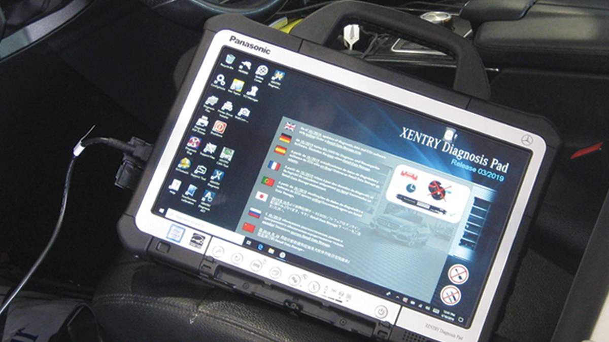
So let’s look at a hypothetical situation that is not all that uncommon the real world. First off, having a XENTRY system with Star Diagnosis is really key to being able to accurately and in a timely manner be able to diagnose faults in fiber optics of a Mercedes-Benz. A factory compatible scan tool that can read “actual values†and “specified values†is a must. You can theoretically diagnose without one but why would you even try? And as mentioned above it’s helpful to be able to generate or command a wake up signal in the system.
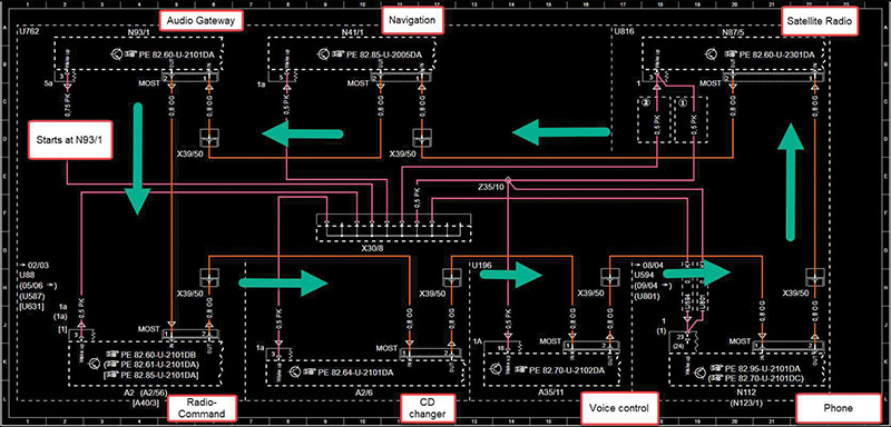
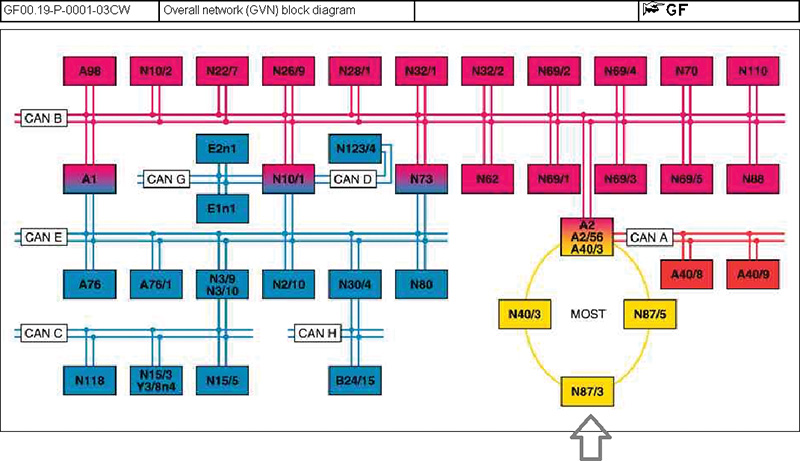
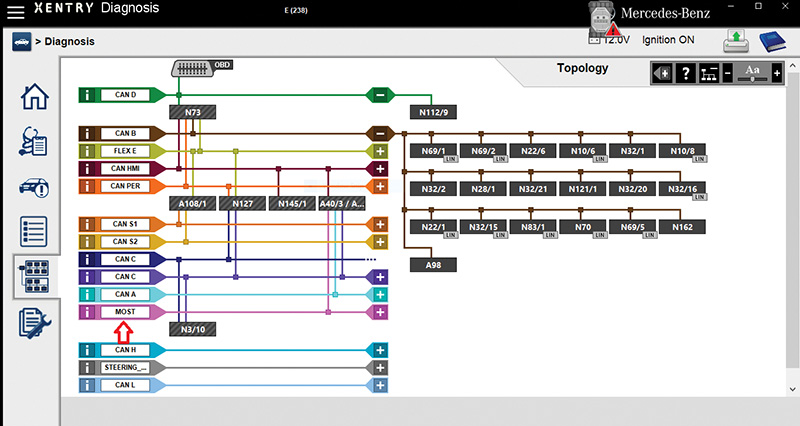
Look at the network diagram of the vehicle in question, taking into account the installed components, and familiarize yourself with the order of the components. You can see the MOST connectors and the “in†and “out†of each component. Let’s say you have a customer concern of no audio.
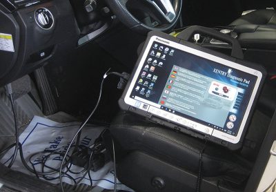
Hook up your factory compatible scan tool, XENTRY or SDS and Read/Record/Diagnose faults. Erase faults and complete a function check of the audio system.
You may see fault codes of U1117 (or D117): Specified/actual configuration of MOST ring differs. In this case look at “actual values†versus “specified values†in the command audio system. If the MOST ring configuration differs from actual to specified, there may be a component or fiber optic cable bringing the network down. Here’s where you need access to the “as built configuration.â€
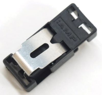
Perform a wake-up line test in actuations to determine if a component on the ring line is not responding. A MOST splice connector can be used to bypass the component (Mercedes-Benz Part A000 545 44 84 available from your Mercedes-Benz dealer) to see if audio comes back. If audio does return, verify power, ground, and wake-up line to the offending component. If voltage testing shows ok, you’ve found the problem and you can replace the component. If you can’t send a wake up signal, check the optical system: Unplug the fiber optic and look at it for a flashing red light when the radio is turned on. An absence of a red flashing light could mean that the preceding component may not be responding. You will have to install the splice connector in each component in its order to eliminate the culprit.
If all components on the MOST ring line are responding, a close look at the fiber optic network will need to be made. Any sharp bends, cuts, scratches can cause static, screeching noises, or no audio due to light (data) loss. (We’ve even seen another installer, thinking it was a wire, try to use a ‘Scotchlok™’ connector to tap into the fiber, which of course damaged it beyond repair.)
What other codes might you see? D016 MOST communication has a malfunction “position of ring break cannot be identified,†or D018 MOST communication has a malfunction “ring break at position 1,†are stored in the head unit or master. In this case the master is telling you it thinks it knows where the fault in the system lies, at least where in the order of configuration. This is where sometimes it can get a little confusing. For example, the MOST configuration listing may show 1) COMAND Unit, 2) Sound Amplifier, 3) Satellite Radio, and 4) Media Interface Control Unit. However the Position(s) are numbered in reverse order (counter-clockwise) from the Master. Position 1 in this case is the Media Interface Control Unit. If you look at the actual MOST diagram (not to be confused with the configuration ring), you can see the direction of the flow. Now if you have the capability you would send a wake up signal to the Media Interface control unit but in any case you would need to again install the optical splice connector and see if the fault is corrected. Always confirm that the component you suspect is getting good power and ground. We always recommend a voltage drop test just to rule out any bad connections interfering with the proper operation.
You always want to perform due diligence as most components in the system can be quite costly, so it’s good practice to confirm that the actual and specified coding of the components match each other and that the coding is in the correct order for the vehicle. Remember each model has a specific order of how the modules are to be configured, and that each vehicle has its own list of installed components. If the MOST master “sees†the electrical wake-up happen in a different order than what is programmed, you are guaranteed that the system won’t function.
While audio problems are rare, and ring configuration errors are even rarer, it’s always good to understand how the system works so you can be more efficient in your troubleshooting and, of course, successful repairs.



0 Comments