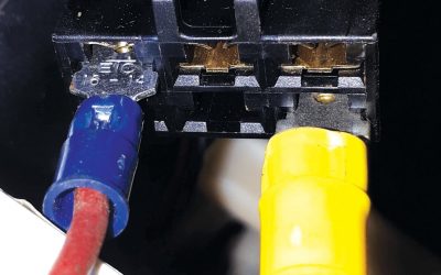
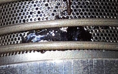
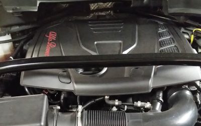
As long as electronics have been around and as long as they will exist, someone will always try to economize on circuit materials. When too much current is applied for the circuit materials to handle, the electronics overheat. Heat is the skulking menace of electronics. If all the heat could be dissipated effectively, most electronic circuits would never fail. In defense of certain designs, circuits must often be downsized to fit in the space available, creating other heat-dissipation problems — especially in combination with limited ventilation and additional sources of heat. Whatever the reason, we can count on many electronic circuits to fail eventually from heat. I guess this is a good thing for repair technicians— our future at least is secure.
The subject vehicle for this article is a 1996 Nissan Quest. These same vans were also sold as Mercury Villagers, but behind either badge, the vehicle design is definitely Nissan from bumper to bumper, including the engine control electronics and the Nissan 3.0-liter V6. The customer com-plaint on this Quest was lack of HVAC blower operation in the rear passenger compartment. Excess circuit heat in front had left the owner with no control of the passenger-comfort heat in back.
The Layout
When it works, the Quest’s rear blower motor can be controlled from either the front or rear compartment. The rear compartment controls (Photo 1) are behind the driver’s seat and provide control of temperature, fan speed and vents for the rear only (Photo 2). A panel below the controls (Photo 3) allows access to the rear blower motor and resistor. The panel is easily removed and is the quickest way to check for circuit voltage.
The driver’s HVAC controls (Photo 4) are in the dash panel, to the right of the steering wheel above the radio. The front controls always determine front temperature, vent settings and fan speeds. In addition, the driver can adjust the rear blower speed by moving the fan control lever at the bottom of the panel. Selecting REAR allows the rear seat passengers to control the rear blower speed, while selecting OFF turns the blower off. If the driver selects 1 through 4, he can also control the speed of the rear blower.
Circuit Design
Creature comforts often sell cars. However, every time the designers come up with a new comfort feature, they also create a new set of potential failures. The level of control in this system requires a wiring design more interesting than most. Nissan runs the rear blower current through the main controller, and the main controller is in the front control panel. Luckily, the system is not overly complex, and access to the individual components is amazingly easy. As previously mentioned, you can access all the rear components after removing a vented panel.
Gaining access to the front controller is more difficult, but still possible. First, remove the trim panel from the stereo and HVAC panel (Photo 5). Then remove the stereo and HVAC panel by removing the Phillips screws. This allows complete access to the wiring for all necessary voltage tests. Before doing any testing, however, learn how the circuit functions. It may look overwhelming at first glance, but if we break the subcircuits in the wiring diagram down, we can understand the system’s operation. If we don’t break it down and don’t learn it, it will be overwhelming.
The entire HVAC system-wiring diagram is rather large. We extracted the rear blower circuit from the full diagram (Figure 1) because that’s the focus of the original complaint. The simplified diagram may still be confusing, but if we examine it closely, we can see how the system works. The REAR BLOWER ON label is an input to tell the controller when the blower is commanded ON. This input is high when the circuit is OFF and low when the circuit is ON. In Figure 2, red indicates battery voltage, and blue indicates zero volts, the groundside of the circuit. Since both switches are OFF, a voltage check anywhere on the red circuit should indicate battery voltage.
To see how current flows through the circuit, let’s color the wires to show only where current flows. The black wires will have voltage but not current. By turning the front switch to REAR and the rear switch to 1, we can see the blower motor current flows through the fuse, motor, resistor, rear switch, front switch and to the front control unit, where it is grounded via internal circuitry to an external ground (Figure 3). The REAR BLOWER ON input will be low. With current flowing through all three resistors in series, the blower motor spins at its lowest speed.
Another switch position shows how the driver can take control of the rear blower and how that still signals the rear A/C control unit (Figure 4). Current flows through the fuse, the motor, the two resistors, the front switch and the front control unit. This pro-duces a higher fan speed because of the lower resistance through the resistor unit. The pink circuit shows how the rear control unit still sees blower operation. The voltage should be near zero volts, even when the switches are on the higher speeds.
Notice that the rear control switch is in the HIGH or 4 position, but that doesn’t affect current flow. The current can’t flow through the front switch, and there is no alternate ground source for blower current. This configuration gives ultimate blower control to the driver.
Diagnosis
A thorough understanding of the blower circuit allows us to diagnose any problem. Remember the complaint is ‘no rear blower operation.’ We confirmed the rear blower does not function with either switch. The front blower worked normally. Several components could cause this, but the easiest to check is the blower motor itself. With the panel removed (Photo 3), check the voltage on both sides of the motor connector. This vehicle showed battery voltage at both wires, telling us the fuse is good and the problem is in the ground side – power got to the blower motor, but not from it. It was also easy to check all four resistor wires at the same time. These turned out to have battery voltage as well. Changing the positions of the switches had no effect on the readings.
It’s time to decide what to disassemble and test next. Looking at the wiring diagram, we see the rear switch could be taken out of the circuit but the motor could still work. But the front switch must function for a complete circuit to exist. The front A/C control unit must also function or the ground circuit will not be complete. These two components are in the same location, so we removed the front HVAC panel next.
On the back of the controller (Photo 6, page 30), you will notice two heavy-gauge wires in a two-terminal connector. These correspond to the REAR BLOWER CONTROL and GND terminals in the wiring diagram. We connected the meter to the REAR BLOWER CONTROL wire and read battery voltage.
Moving the meter to the other wire, GND shows zero volts. This tells us the ground for the controller is good, so there must be an open inside the controller between these two terminals. Now we can be confident that replacing the controller will restore the vehicle’s HVAC system to proper operating condition.
To see the internal circuitry, we took a photo of the controller with its cover removed (Photo 7). The orange/red wire connects to the front panel blower motor switch, and the heavy black wire connects to ground. Removing the circuit board and turning it over revealed the source of the problem. A black spot on the board marked the location where the relatively high blower motor current was too much for the small circuit board. This dark black spot was all that was left of the circuit at that point. This part of the printed circuit had become a second fuse for the circuit.
Even though these controllers are a common failure item, don’t short-cut the testing procedure. Checking circuit volt-age at the rear blower motor is quick and easy. This will confirm the power side of the circuit before you disassemble the front panel.


0 Comments