

This specific HVAC system has no self-diagnostic abilities, but does control the blend doors and A/C while manually controlling the blower motor speed.
This article is intended for the learning technicians that have an interest in diagnosing and testing a Hyundai HVAC control system. This specific HVAC system has no self-diagnostic abilities, but does control the blend doors and A/C while manually controlling the blower motor speed.
The Back Story and Customer Conversation
This specific Hyundai arrived with the vehicle owner and we spent the time to question the driver about his issue. During the conversation, the driver expressed his version of “research†and what parts he replaced in addition to the path the “research†took two people. Their interesting journey leads back to the beginning. The blower motor did not operate with any speed control. One part they decided to purchase and replace was the blower motor resistor. The vehicle owner left the original component in the vehicle.
What Are the First Steps?
Thankfully the missing glove box screws were found in the cup holder, and a complete scan offered a few details that required additional proof. The HVAC system was not displayed within the vehicle scan. The proof will be within the wiring schematics for the HVAC and DLC.
The wiring schematics established the fact that the HVAC controller has no self-diagnostic abilities within this specific model.
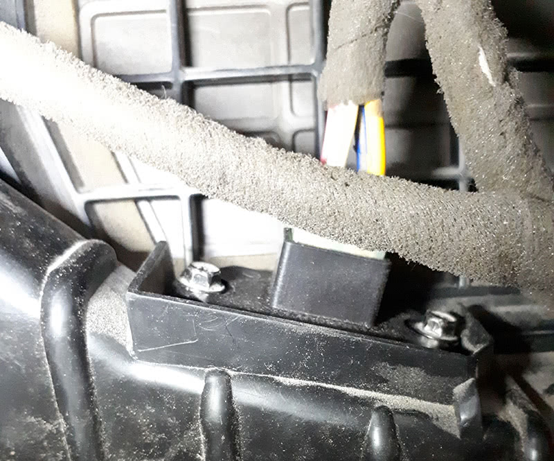
The primary inspection with the glove box removed indicated that the replacement blower motor resistor and blower motor are connected.

| System Name | State |
|---|---|
| ECM (Engine Control Module) | OK |
| TCM (Transmission Control Module) | OK |
| ABS (Anti-lock Braking System) > 2WD | Fault | 2 |
| ABS (Anti-lock Braking System) > 4WD | Fault | 2 |
| ABS (Anti-lock Braking System) > Traction Control System | Fault | 2 |
| SRS (Supplemental Inflatable Restraint System) | OK |
| Transmitter Code Saving | OK |
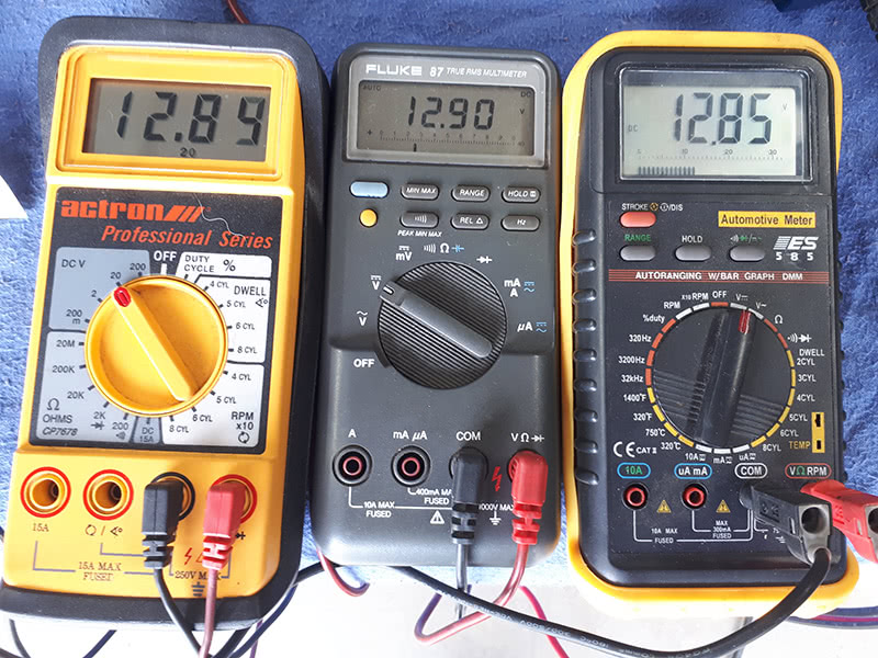
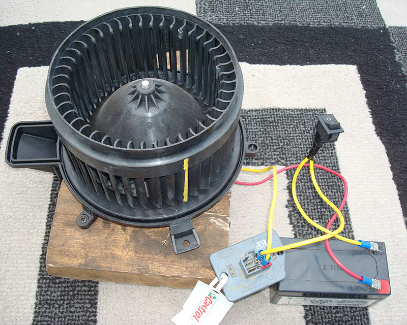
With either a vehicle or external power source, the connection at the blower motor was disconnected, and we applied the B+ power and B- ground source. Using the schematic, the B+ and B- connections should operate the blower motor at high speed. The test battery was scavenged from a scrap Mercedes, but any supply can be used for quick testing. This simple test and with a simple 2- wire bladed connections proved the blower motor operated for this test.
| Special Note |
|---|
| Not all meters (DVOM) with cables work identically to each other. These meters were all attached in parallel to the test battery. |
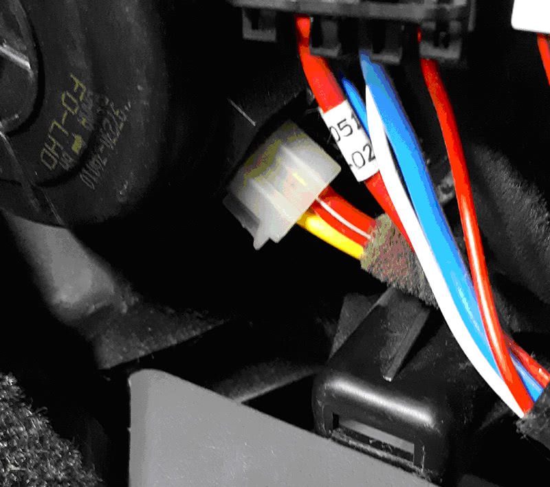
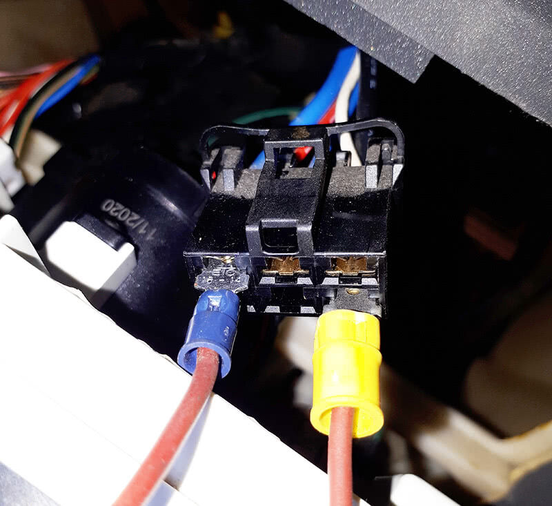
Again, with the aid of the schematic, the red/white wire will be the B+ connection. The temporary ground path is the yellow connection to the temporary B- body ground path or battery B-. Reconnect if it passes.
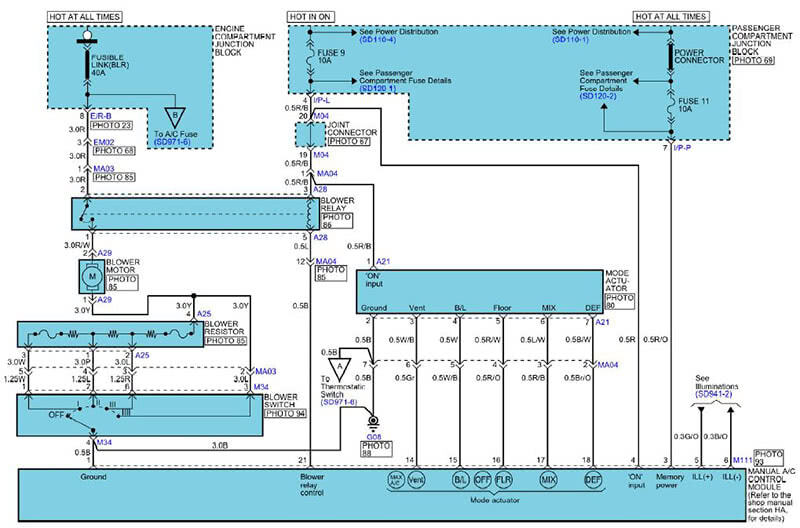
With the blower motor connected, it should operate. With the circuit intact, all is true providing the blower relay closes. The ground or control for the blower relay is at the manual A/C control module. It is the black connection named Blower Relay Control Pin 21. Proof of relay operation (KOEO) is grounding that connection. That control will close the relay and apply B+ to the blower motor red/white wire.
The yellow wire will complete the current path and control motor speed through the blower resistor. Via the driver blower motor speed switch and resistor, the current path is completed at the black body ground wire G08.
How to Control Speed and Find the Fault
Follow the current path with the schematic. The blower relay has two power sources, the control is fuse 9, 10 amp, and the high current source is fusible link (BLR) 40 amp. The relay control is with KOEO. The 10 amp fuse 9 also powers the manual A/C control module Pin 4. Pin 1 of the manual A/C control module is the B- connection and connected in parallel to blower switch Pin 4 to ground connection G08.
The current path is followed from the blower motor yellow wire Pin 1 to the blower resistor Pin 4 and parallel to the blower switch Pin 3. This proves the current path should be correct for high speed.
So Why is There No Control or Fan Operation?
The front fascia where the blower switch resides has a few screws within the ash tray and the rest of the panel is a “friction†fit with clips. Plastic pry tools are required to pull the panel away from the dash and expose the blower motor speed switch.
Continue to Prove the Fault
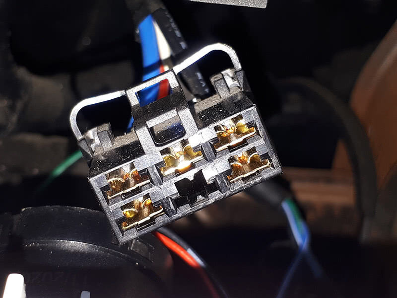
It will become obvious there is no ground path, and the connection behind the blower motor control switch harbors a secret. With a hand made wire with two male blades, we attached the connection to each corresponding female terminal. The by-pass connection controls the blower motor speed.
| Pin 4 Black to Pin 1 White | Speed I |
| Pin 4 Black to Pin 2 Blue | Speed II |
| Pin 4 Black to Pin 6 Red | Speed III |
| Pin 4 Black to Pin 3 Blue | Speed IV |
Adding the bladed connections allowed the blower to rotate at all four speeds and proves a defective switch assembly.
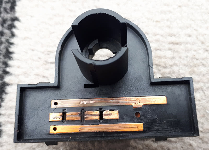
The original switch was opened and found to be overheated. The high current draw began to melt the plastic shell holding the copper connections. The copper connections were also contaminated.
The ordered/replacement switch had the blower motor operating normally.
Just One More Thing ~ Lt. Columbo
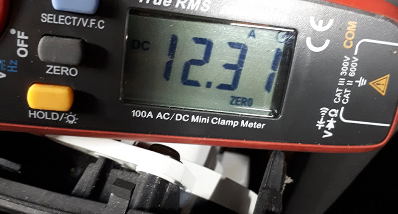
There have been some documents that discuss the current draw with the blower motor at high speed. Between Pin 4 and Pin 3 (high speed IV) the current draw discussed and should be less than 20 amps. Attach an amp clamp and measure the draw at the hand made wire connection for speed IV.
| Note |
|---|
| If the blower motor amperage is greater than 20 amps, expect the blower motor to overheat and likely damage the blower switch or blower motor resistor for similar models. |
Be aware, the amperage measured will be total amperage between the ignition switch, battery, 40 amp fusible link, blower relay, wire crimps, fasteners, ground connection, and any switch or bypass to operate the blower motor. The test within the vehicle and the blower motor at high speed averaged close to 12.31 amps.
What About a Bench Test?
What if a blower motor, blower motor resistor, battery, amp clamp, DVOM, and a set of connected wires creates a simple bench test? Can we apply this test with a schematic, using the shop DVOM and amp clamp?
Can the current be tested through the blower resistor to ground and measure the voltage change at each connection? What is the relationship?
This test proves the original “research†was incorrect by the individuals that attempted the repair. Since the vehicle was now delivered, why not use a new blower motor from a Jeep, connect the original Hyundai blower motor resistor, and test the operation at different speeds?
The experiment will indicate the voltage changes at the battery, and voltage differences at each blower motor resistor connection. Each speed test will measure the current draw within the desired selected speed.
The Bench Setup
Using the schematic, a new fan, battery, wires, and original blower motor resistor were connected for this “learning adventure.â€
This test also includes the blower motor switch condition and blower motor resistor test via factory values.
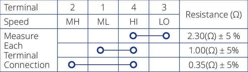
The three resistor speeds are measured from 4 – 3, 4 – 1 and 4 – 2.
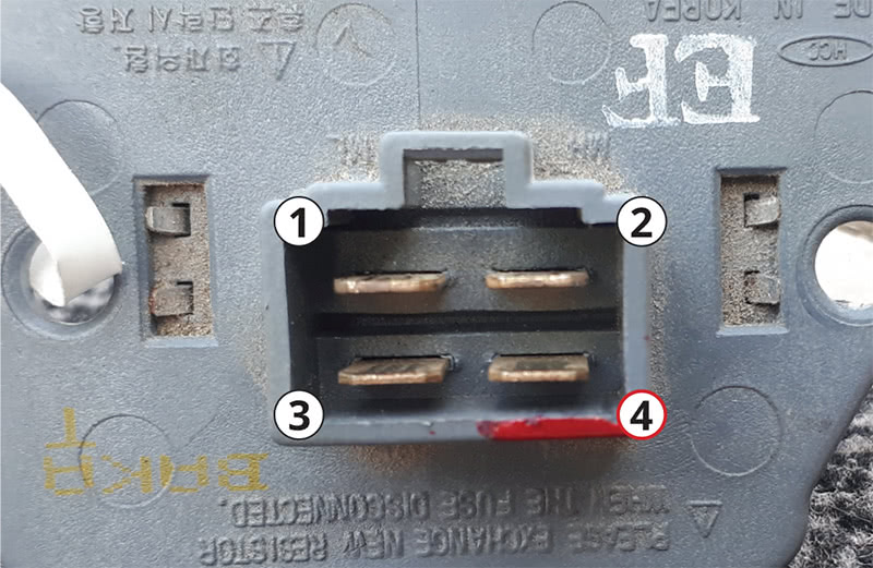
Use the corresponding template. Marked in red (photo) is Pin 4. The yellow wire is the ground return path from the blower motor. Moving the “B- switched†yellow wire to Pins 3, 1, or 2 changes the blower motor speed. A direct (by-pass) connection to ground will spin the motor at HI speed.
Live bench tests with a battery charging at 15 amps is about 15.00 volts
| Connection | Pin Test | Battery Test | Amperage |
|---|---|---|---|
| LO Pin 4 – 3 (2.7 Ω) | 9.27V | 12.83V | 03.97A |
| ML Pin 4 – 1 (1.3 Ω) | 6.99V | 12.26V | 06.81A |
| MH Pin 4 – 2 (0.6 Ω) | 4.30V | 11.63V | 11.64A |
| HI Speed to B- | 225.2 mV | 10.71V | 20.37A |
Kindly note, the preceding test was with a small battery with a charger/maintainer attached. A full sized battery will offer slightly different results.
The Basics of Ohm’s Law
If resistance is increased, the measured current drops for any given voltage.
If resistance is decreased, the measured current rises for any given voltage.
Paraphrase: If resistance is high, current is low, and if resistance is low, current is high.
Therefore, with factory specifications and an operational blower motor resistor, these values will hold true and makes for an interesting learning adventure. Everything will depend on the condition of the blower motor.
The basic relationship for resistance and current of Ohm’s Law applies.
As an addition to this article, why not measure the rotational speeds of the spinning member on the work bench?
What About the Motor Speed—Can It Be Measured?
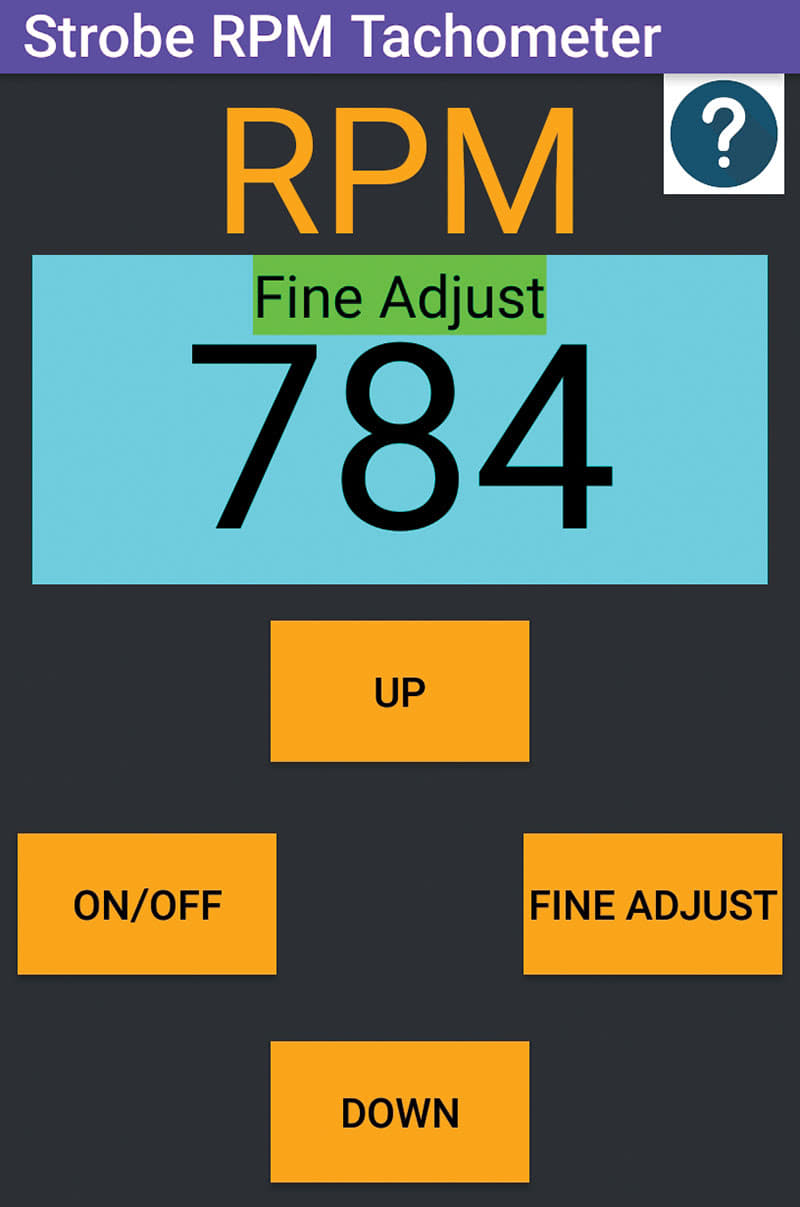
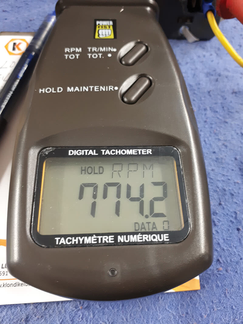
What tools can safely measure the rotational speed of the motor? Three tests were accomplished and offered near identical values. Two with an Android device that uses the camera flash to pulse and “align†a mark on the rotating blower fan, and another is a laser rpm device that reflects the light via a “reflective†sticker on the rotating blower fan for an rpm calculation.
Testing spinning members must also be 100% safe if tested. The rotational speeds can also include the: alternator, A/C compressor, power steering pump, water pump, idler wheels, drive shafts, etc.
In the near future, this will include rotational speeds that can measure the direct relationship of rotating members that may vibrate within a specified calculation. The calculation will include the view of the frequency spike.
The calculations and measurements will narrow the search for a vibrating/rotating member(s) with minute disassembly to the exact calculated frequency of the offending rotating member.
More on this research and technology later.
Android Flash vs Laser Reflector
A vertical paint mark and reflective sticker were introduced to the blower motor fan to test the rotational speed. The Android application took a few steps to have the “vertical paint line†viewed for yours truly. With some fine tuning the screen capture was saved-View the video here: https://youtu.be/gS3Wmues6_k
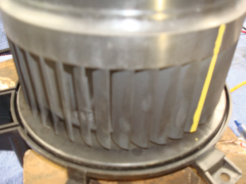
The same camera was used in the attempt to capture the vertical line while the fan was rotating. Out of the 15 attempts, two still images captured the yellow mark for the experiment. The image named “Camera capture†was taken in conjunction with the Android device with a co-worker. Notice the flash reflection on the motor fan.
The added link with a video will show what the user is seeing when calculating the rpm with the Android application. It may not be perfect, and requires fine tuning, but the values are relatable and relative to this experiment.
The next experiment was with the laser rpm tool. This tool will read live values and save the values within the tool. The laser rpm tool and the Android were quite close in the rpm speed calculated at the LO speed connection. The laser rpm tool will require a reflective sticker to calculate the rpm. The best option is to have the laser tool approximately 30 cm from the reflector.
What Was Learned
The noted resistance, voltage, and current tests can also be applied directly to the vehicle with all the components intact. In some cases, extended wires with connectors may be required. A bench test will accomplish these same tests with anything that is attached and will follow the vehicle schematic(s). The values may not be identical but proves whether the components operate or not operate and will follow Ohm’s law (resistance/current relationship) within this specific case.
Meaning: All blower motor fans with a resistor operate identically.
The final scan should indicate any other faults or anomalies attached to the Hyundai being tested.
| System Name | State |
|---|---|
| ECM (Engine Control Module) | OK |
| TCM (Transmission Control Module) | OK |
| ABS (Anti-lock Braking System) > 2WD | OK |
| ABS (Anti-lock Braking System) > 4WD | OK |
| ABS (Anti-lock Braking System) > Traction Control System | OK |
| Transmitter Code Saving | OK |
| Tools Used |
|---|
| Wiring schematics |
| Launch EasyDiag |
| 2 Multimeters and amp clamp |
| Android device with strobe rpm tachometer application |
| Battery, On/Off switch with wired connections |
| Digital laser tachometer |
| 15 amp charging device |
| Camera, pen, paper, and screen capturing software |
by Agostino (Augie) Ferron


0 Comments