

How can an investigation go from bad to worse and solve these issues in a cost effective manner?
Back Story 1
The Tucson arrived at the repair facility because the Check Engine light was illuminated, and secondhand information indicated that “The engine tended to run rough.â€
A quick simple scan did indicate faults, and everything was captured with KOEO and a 90 amp floating power supply attached to the battery.

The Tucson came to the facility under its own power, started in the parking lot, and the engine ran in the service bay for the initial group of tests. Be aware, this is a GDI (Gasoline Direct Injection) engine with variable valve timing on both the intake and exhaust banks.
This GDI engine ran smoothly during the first group of tests.
Pay attention to the first set of scans and see where this leads.
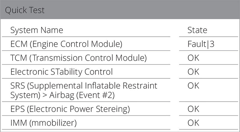
This following image and fault codes offer a clue of what the customer complaint is during the scan, but can it be tested easily and duplicated?
Note that during the scan the engine was loaded lightly by applying the brakes and a little throttle while in gear. This generates more heat in the transmission, more quickly. Of course, it is not a good idea to apply WOT here, but slight momentary throttle application will force the engine VVT assemblies to activate. When activated, the difference can be seen when testing the VVT angle changes for the engine controller.
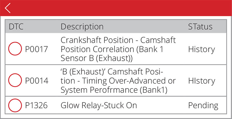
One interesting mention is fault P1326 Glow Relay-Stuck On.
Obviously, the engine tested is not a diesel model and, somehow, the fault is “lost in translation.†The P1326 code is a knock sensor fault.
This “corrected spelling†fault is due to the noise the engine management system is experiencing when the cam phaser(s) is/are experiencing a fault at idle or under slight load in gear. This particular VVT fault/defect may also exhibit engine noises while running. The engine management system will exhibit immediate “limp mode†when the fault is recorded via the knock sensor and limits engine performance.
The noise heard under slight load in the service bay, and the correlation recorded, can also be possible because of LSPI (Low Speed PreIgnition). LSPI is an inherited condition with direct injection engines when mixtures of oil and fuel are self ignited during the compression stage. And with glowing particles found in the combustion chamber, this is possible.
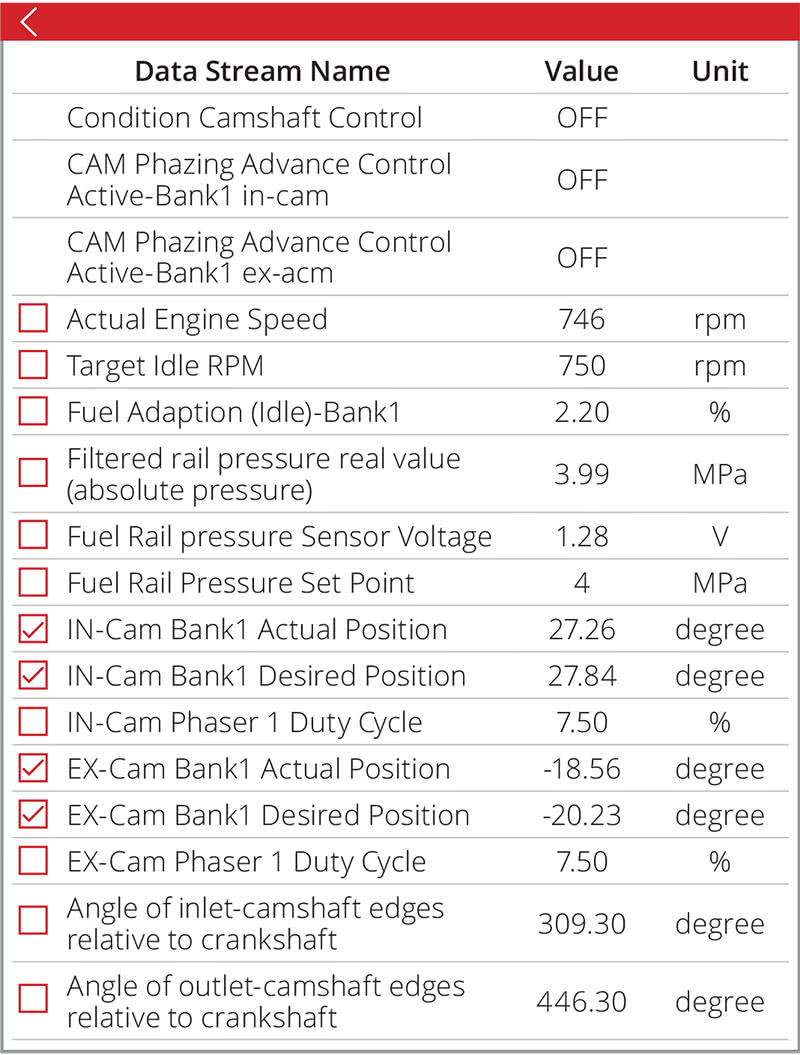
Is There a Measurement, Is There Proof?
Within the service bay conditions, it was quite obvious the intake cam was operating normally, but the exhaust cam definitely exhibited the incorrect position in degrees between the actual and desired angles. At idle or under load in gear, the expectation should be close between the two and should follow. This engine varied the angles between 1.67 and 2.24 degrees at idle. It would appear the timing chain is stretched or the VVT mechanism is damaged.
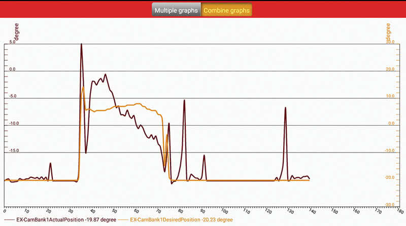
What Does The Service Bay Test Indicate Under Slight Load?
Each spike within the graph indicates a slight throttle burst while also held under slight load in gear. In other words, both angles should follow each other with slight load.
The customer was summoned to the facility to provide more information. This is because of the yellow paint markings on the engine covers.
Missing and damaged retaining clips for the injectors were also noticed.
Back Story 2
With a direct conversation with the vehicle owner, much more information was gathered about this Hyundai.
1) It was purchased at a used car lot out of the city and the used car lot kept one of the keys.
2) The engine self destructed some time after the purchase.
It was replaced by the customer (another shop) with no warranty from the used car lot.
3) This Hyundai experienced an occasional no crank/no start soon after the purchase (no starter revolution).
The used car lot said “The car needs a reset.â€
The facility that replaced the engine did not experience the no crank/no start condition until the customer retrieved the Hyundai after the engine replacement.
4) The vehicle owner expressed that the no crank/no start happened multiple times, and getting it to run was like “constant coin tosses.â€
5) After the initial tests with P0017 and P0014, we experienced graphs that told a very interesting story at idle and under slight load.
What Was Found?
This Hyundai has a used engine and the oil is clean but slightly over filled. The customer was advised to use only SN-Plus oil for this direct injection engine and nothing else because of LSPI, and that certainly includes a recommendation to use a better fuel quality.
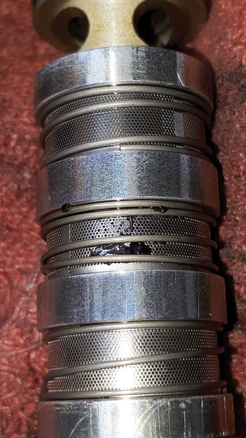
The scan tool data led to the oil control solenoid, and we found the screen damaged. One can imagine the metal particles of the screen hindering the operation of the spool within the oil control valve.
The image “Defective Oil Control“ (page 1) was taken with a magnifying application installed into an Android cell device. The next step was to find a replacement oil control solenoid.
Guess What Happened Next?
The incorrect aftermarket part was sent. The fastening bracket was not in the correct position, the solenoid was too short, and the connection to the harness did not fit.
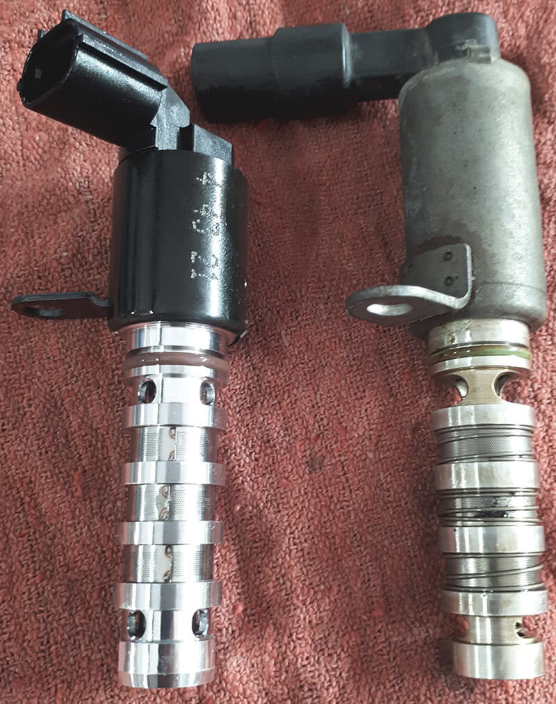
The replacement component had to be reordered and, in the meantime, the original was reinstalled to get it out of the bay. It would appear that the incorrect part was in the box that matched the aftermarket listing.
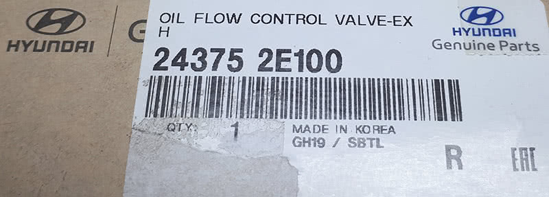
Another oil control valve arrived the next day and it was incorrect again. We all would hope the “powers that be†get with the lesson plan. Disassembly was not required because the first replacement was retained and matched the incorrect reordered version. This time, an order for the proper oil control solenoid was placed with the dealer.
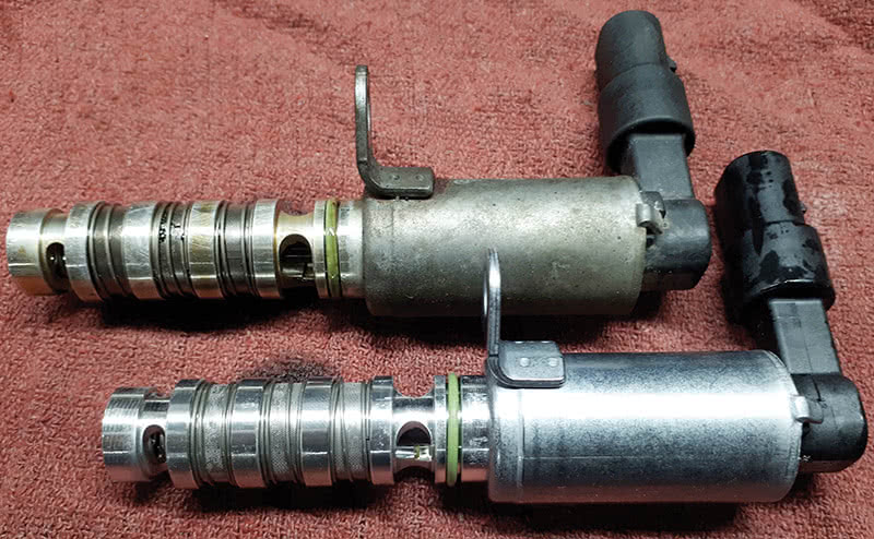
The Difference Between Aftermarket And Dealer Components
The third try is not a cost effective way to pay for service bay overhead.
There is a difference between the aftermarket and dealer components:
- The dealer parts fit.
- The dealer parts have a great warranty.
- It is rare that a dealer part fails after it’s installed.
- The dealer parts pricing is competitive with the aftermarket.
| NOTE |
| Warranty companies are notorious for attempting to dictate labor and/or parts costs for a vehicle that requires warranty repair. So be prepared with detailed documentation to justify your costs, or you can expect a can of worms to reside at the service desk. |
The final test was with the graphing ability of the Android application, and we noticed the difference between the screen images “Defect test†and “New test.†Of course, all fault codes needed to be deleted and we needed to start measuring again from a cold to a hot engine. We tested at idle and with a slight load in gear.
We began by cleaning the exhaust side bore and lubricating the o-ring.
We dipped the new component into fresh oil, making sure the electrical connections were clean and serviced with Stabilant-22. Stabilant-22 is a polymer contact enhancer and never to be used on oxygen sensor connections.
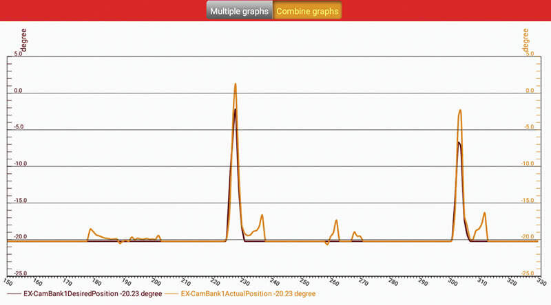
The image “New test†indicates that the engine management system recognizes the desired and actual position in degrees following each other while in the service bay.
No noticeable noise was recognized at the knock sensor data.
The engine noise was not experienced and no fault codes returned. What were the chances the vehicle would exhibit the no crank/no start to yours truly? When advising the vehicle owner “It runs great now†when completing and leaving it in the lot that evening, it became “just one more thing†~ Lt. Columbo.
The next morning the Hyundai did start and we got it into the service bay.
Armed with a schematic, the starter relay was found and oddly, when moving the relay in its mount, the starter would engage with the ignition key removed.
From that moment on, that Hyundai would not crank or start.
Remember the first sentence, “Cost-effective manner?â€

The Fix Is In
We developed a bypass to guarantee the Tucson would start every time. This test had the engine running quickly.
This solution is affordable and quick to apply. The relay is now removed for the bypass and later reinstalled.
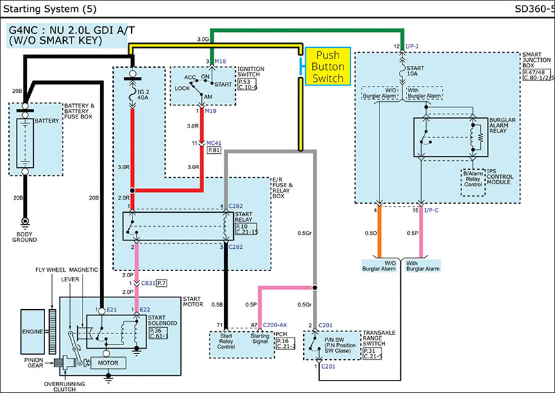
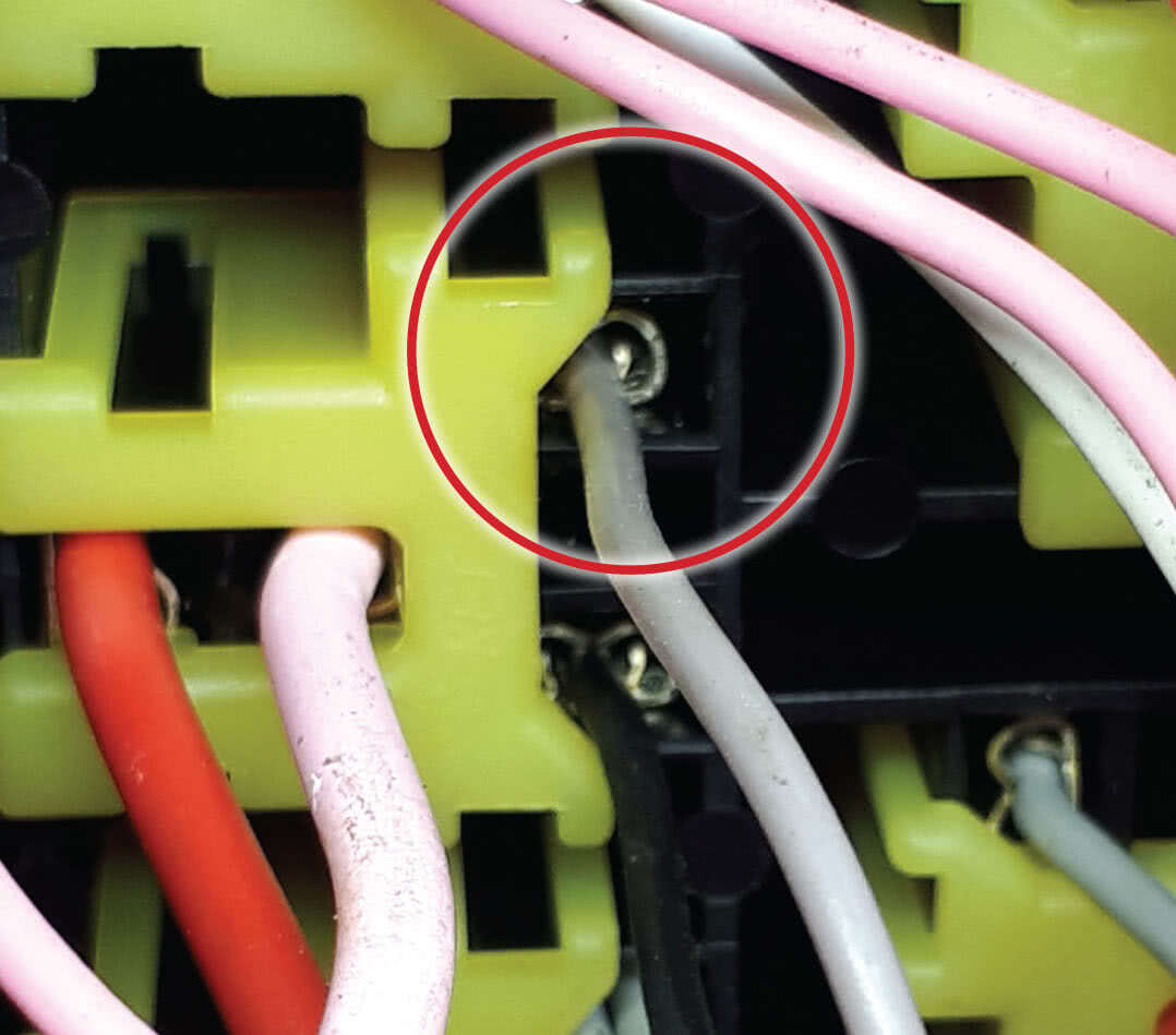
The first step was to identify the relay panel and starter relay. (See “Starting Circuit†image.)
Circled in red is the temporary relay taken from a scrap BMW. A new Hyundai relay was ordered because of its amperage rating.
Required is a 35 amp version; the BMW is only 20 amps. It is temporary because the original was not trusted any longer.
We opened and separated the under cover of the fuse panel to safely expose the harness. A temporary/extended wire was also attached between the fuse panel and the battery positive cable so we could turn the panel on its side. The connection is illustrated in yellow. (See “Relay Panel.â€)
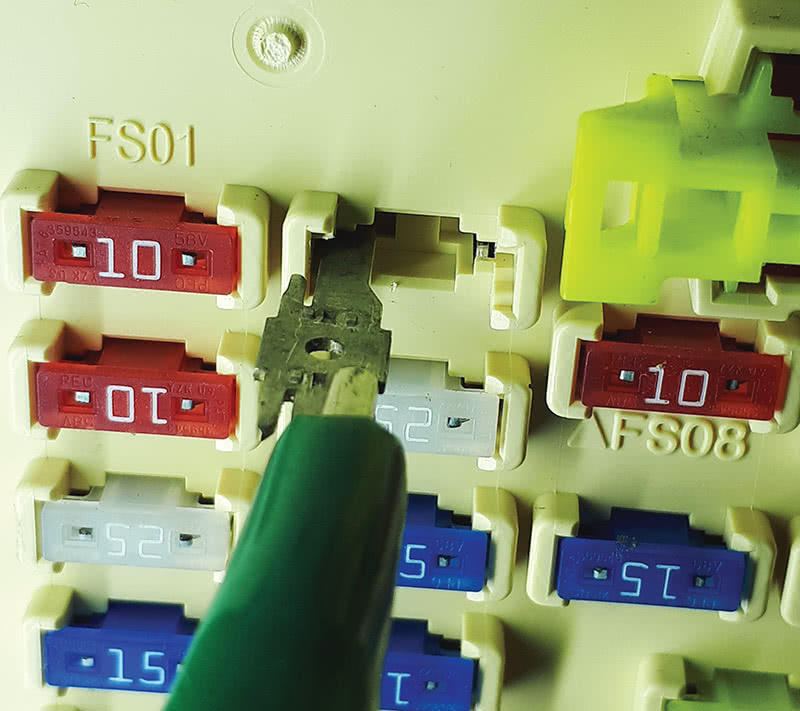
The fuse identified as START 10A is within the Smart Junction box and is powered with the ignition key in the On position. The fuse was removed and we applied a blade to the “hot†side. These blades are scavenged from defective GM fuse panels, desoldered, and all kept in a special stash.
We tested the power side as described and, with a jumper wire, inserted a needle (see Test 1 and Test 2 to continue the test and follow the power source to the starter relay).
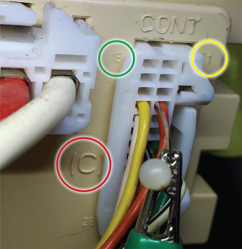
The red circled “(C)†(see image “Test 2â€) is indicated in the schematic as I/P-C, and the orange wire is at Pin 4. The yellow circle indicates Pin 1. The schematic also indicates Pin 15 and is in green. That wire does not exist on this car because this version does not have a burglar alarm. The ignition switch start command is read at Pin 4.
The red circle in Test 3 is Pin 4 C282 of the starter relay. With the jumper wire attached as in Test 1, follow the voltage path. With this test, there was no voltage. At Pin 3 C282 of the starter relay, the circuit was intact.
The connection between Pin 4 of the Smart Junction box and the connection coming out of the transaxle range switch in Park or Neutral was intact. The ECM recognizes the P or N signal to authorize a start at ECM Pin 67 C200-AK. The range selector and data within the scan tool will display all gear ranges correctly. ECM Pin 71 C200-AK (Pin 3 C282 of the starter relay) was active as mentioned earlier. Therefore the ECM had to be defective and finally failed.
The work around is simple.
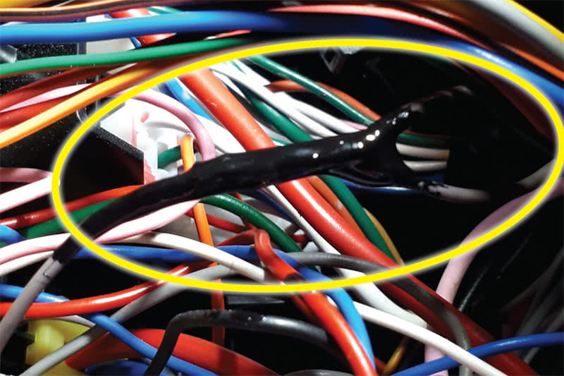
At the gray wire mentioned in Test 3 and Test 4 (starter relay), we cut the wire and added another wire long enough to go into the interior of the Hyundai, and we reconnected (crimp and shrink) all three.
Everything was covered in liquid tape and allowed to dry.
Another wire that is fused was attached at the power supply mentioned in the Relay Panel image (Test 4), colored with a yellow circle. Both wires were inserted into a plastic corrugated tube and safely tie wrapped to the interior.
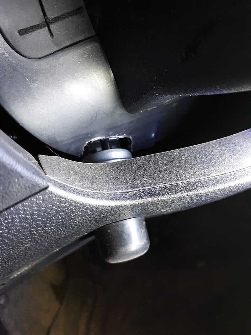
Eyelets were attached to the opposite end with a push button under the left side of the steering column.
The relay was installed as was the lower cover of the relay panel, and it was reconnected to the original power supply.
What We Have Here Is a “Push To Startâ€
With this arrangement it only works in Park and Neutral. The ignition key needs to be in the On position and now the push button will operate the starter motor.
This behaved as normal — one touch of the button and the engine would crank until it starts. Of course the ignition key will kill the engine.
The key On and Accy positions worked as intended.
Test 5 shows the push button very low, at the knee bar and difficult to notice. Using the push button method was a quick, simple, and effective way to ensure this Hyundai starts at all times.
The new relay was installed as soon as it arrived.
It’s been close to a month now and the customer has not complained about a “no crank/no start†condition. This Hyundai still does not start with the ignition key in the starting position.
Last mention, an inductor test tool was used at the ignition switch, the immobilizer is active, and the chipped key is read and recognized via ECM.
The junkyard engine is completely compatible and tests identify an internal fault with the ECM. The internal switching ground control circuit for the ECM is defective. We were able to identify the circuit at issue and we were able to develop a work-around that corrected the symptoms without incurring thousands of dollars of diagnostic time and repairs for the customer.
| Tools Used |
|---|
| Launch EasyDiag with extension cable |
| Android device with Bluetooth communications |
| Fluke multimeter with back probing needles and jumper wire(s) |
| 90 amp floating power supply |
| Wiring schematics |
| Relay breakout test tool |
| Remote starter push button, wires, eyelets, crimp and shrink connection |
| Cutting Dremel tool |
| ¼ inch diameter corrugated tube with tie wraps |
| Camera, pen, paper, and screen capturing software |
by Agostino (Augie) Ferron


0 Comments