
How to discern, diagnose and repair suspension problems when they occur . . .
Almost all Mercedes-Benz cars built since the middle 1980’s have used similar suspension geometry, particularly for the rear suspension. This geometry, beginning with models 201 and 124, is among the simplest and most successful of all multilink suspensions (though perhaps it is odd to describe any multilink suspension as simple). Here we’ll look at why the design is used, at how it works and how to discern, diagnose and repair problems when they occur.
Rear suspension
Independent and Multilink
First, let’s glance over the reasons for independent multilink suspension so we understand what it’s supposed to do. The original vehicle suspensions were on oxcarts, with solid axles bolted solidly to the wagon they supported. If you really want to ‘feel the road,’ you can’t beat a solid, unsprung axle: You’ll get feedback from every twig and pebble; if you drive over a coin, you’ll know whether it was heads or tails. At any speed, you’ll get compression damage to your spine and coccyx, too. This impact is not only uncomfortable for the driver, it quickly destroys the vehicle and its load, too, unless it’s heavy and overbuilt or moves so slowly the road-slams linger over time. Roman centurions stood rather than sat in their war chariots not just because they were macho and studly, but also because that let them bend their knees to accommodate the jolts and lurches of the unsprung vehicle. Riders of stiff-sprung motorcycles today stand on the footpegs while crossing railroad tracks for the same reason.
Leaf springs, mounted either longitudinally or laterally, were a great improvement over that. With enough suspension travel, they could allow the vehicle to traverse very rough surfaces with at least fewer hard slams against the frame itself. Pioneers traveling in Conestoga wagons, however, preferred to walk alongside, and not just to relieve the horses of some load – walking was more comfortable than riding.
 Automotive applications of leaf springs achieved a much higher level of success. In fact, for carrying very heavy loads even today large trucks almost uniformly use either solid axles and leaf springs or, to attune suspensions to load, solid axles with variable-pressure airbag springs. Cars, however, seldom carry loads several times the vehicle’s empty weight; and we expect not only a more comfortable ride, but optimized traction and directional control as well. Hence modern passenger vehicles generally use independent suspensions and coil springs. Such arrangements eliminate the effect one wheel bouncing on an axle can have on the opposite side, reduce the unsprung weight (wheels and tires, brakes and axles, everything that rests on the ground side of the springs) to a minimum, so the road-induced oscillations of the suspension itself affects the passenger compartment as little as possible.
Multilink suspensions ratchet the handling objectives up in a new way. Not only do we want a smoother ride, with less bumping and lurching; we also want better performance and safety. An optimized independent suspension can reduce the perceived inertial effect of bumps, but it does not automatically optimize traction and control. If you think about it for a moment, the only reason a Roman chariot had any traction or control at all was because the centurion’s horses had independent, multilink suspensions (and because horses are heavier than chariots with centurions).
Optimized Wheel Position
For any vehicle, for any load and for any combination of speed and radius in a turn, there is a unique, optimal position for each wheel and tire with respect to the pavement. This position maximizes the treadpatch contact area with the pavement and sustains a predictable and continuous influence on the directional control of the car.
While you can predict some of these positions (we’ll surely want the wheels pointing straight ahead and angled perpendicular to the pavement when driving in a straight line), determining most of the others requires extensive testing and experiment. For example, you want the rear outside wheel to gradually angle inward, to toe inward, as the vehicle leans to that side in an increasingly steep turn. You want this because the contact patch in a turn does not move parallel to the centerline of the wheel, but gradually angles inboard as the turn steepens, up to the point when traction goes away. This keeps the turning angle of the vehicle kinetically or tactually predictable to the driver. However, you don’t want that toe change to continue up to the point when the vehicle suddenly spins. Rear wheel traction must always exceed front wheel traction for obvious reasons of safety.
Similarly, most cars corner somewhat better if the outside wheels pick up a few degrees of negative camber in a turn, to offset the effect of the tilting tire sidewalls. Engineers specify the dynamic suspension angles like caster only after extensive research. When you do your first Mercedes-Benz alignment, you’ll be surprised at the specified caster angle if you learned alignment on domestic vehicles. Some of the older models called for as much as 12 degrees positive. The higher speeds at which people drive in Germany require a much larger caster angle than is common here to ratchet the steering stability high enough for those speeds.
Rear suspension
Traction in turns is not the only objective of multilink design. With careful design of the geometry, the front suspension can resist dips under braking, and the rear can resist dips under acceleration. Braking and acceleration forces also raise the suspension with a force proportional to the acceleration change by the twisting effect they have on the knuckle. Keeping the suspension height level keeps the tiretread geometry straight and square with the road under both acceleration and braking, optimizing traction for both. An anti-dive suspension, in other words, can actually reduce braking distance since it keeps the tiretread flat against the pavement. Similarly, antisquat rear-suspension geometry can improve traction for acceleration. In each case, the height correction maintains the camber on that axle constant. Finally, the right multilink geometry allows the effective employment of truly effective, active suspension systems taking the control of traction and handling to yet a new level (largely quick-adjusting dampers, but also some height adjustment).
Rear Suspension
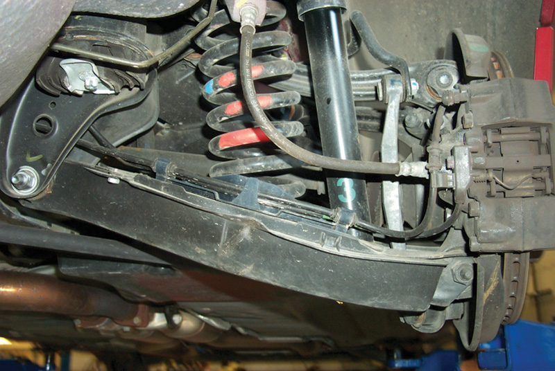
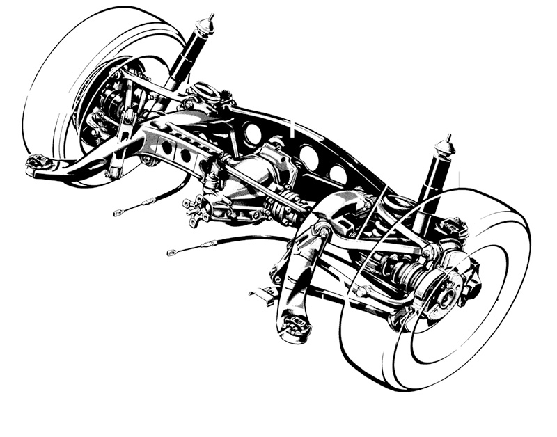
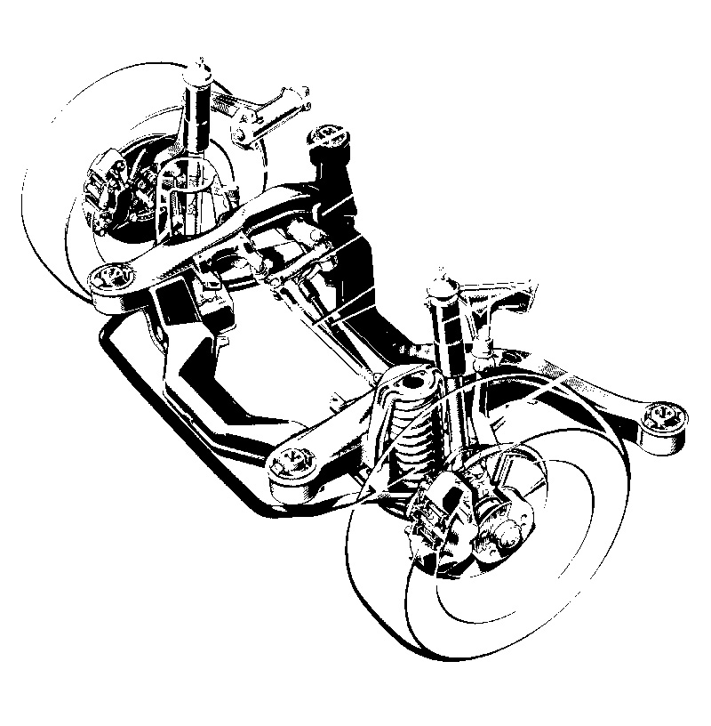
Enough for the theory and the objectives, let’s look at the parts on the car. The rear suspensions of all current Mercedes-Benz cars share the same five-link geometry. The parts, to be sure, are not interchangeable between models, but the geometry is, as we learned in high school, congruent.
The five links are:
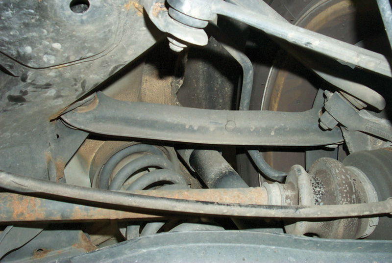
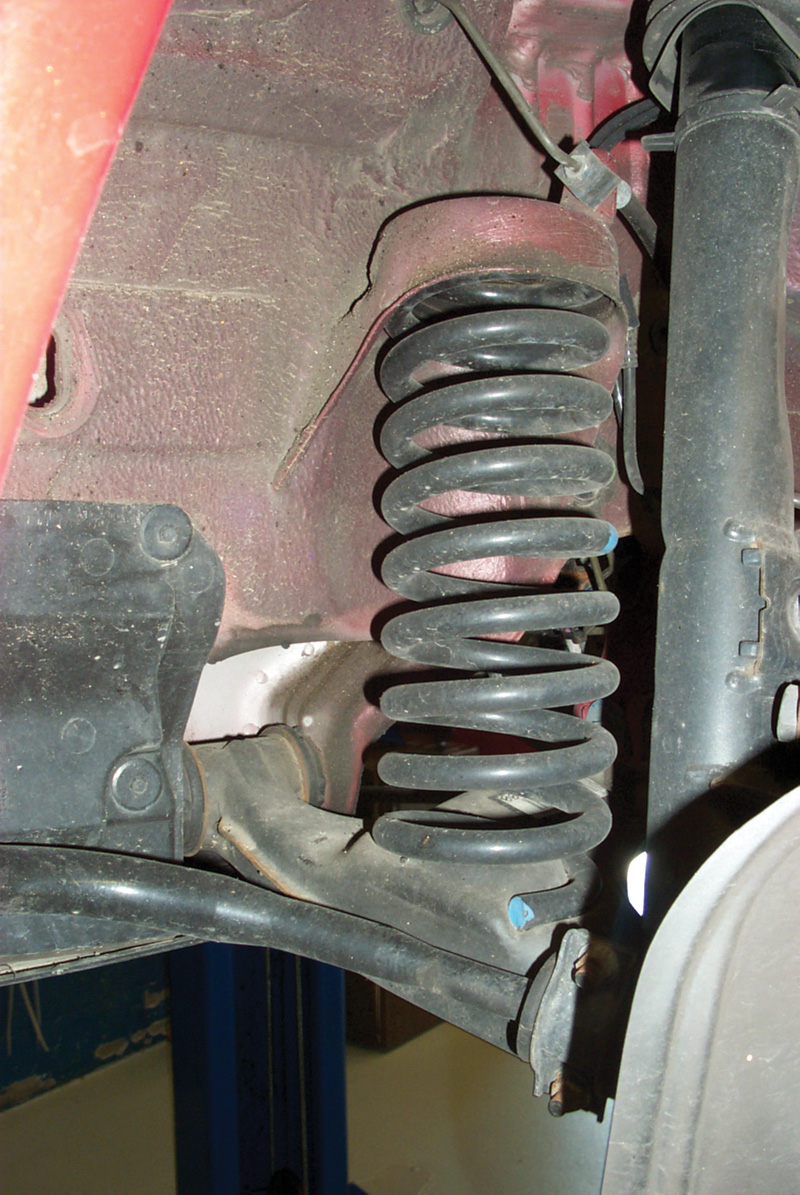
Spring Link
Spring Link
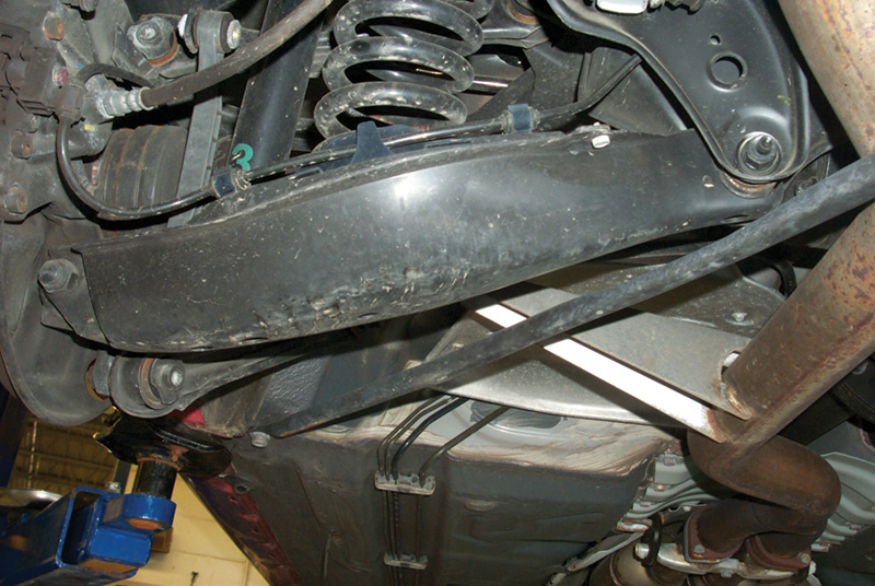
This is the lowest and largest link in the suspension, pivoted inboard at the differential/rear axle subframe and outboard where it forms a yoke with the knuckle of the axle. A bit inboard of the center of the link is the cavity for the bottom of the coil spring, the cavity that gives the link its name. A protective cover bolts to the underside of the spring link, fending off road debris. That protective cover also works as a reliable indicator if there has been collision damage: Since it is the lowest part of the suspension, it is the most likely to encounter an obstacle, and being lighter it will bend or crack before the spring link will.
Camber link
Camber Link
Directly above the driveaxle and the spring link is the camber link, connecting the upper part of the subframe to the upper part of the knuckle. Its function is to keep the tire vertical with respect to the pavement as the vehicle corners or leans.
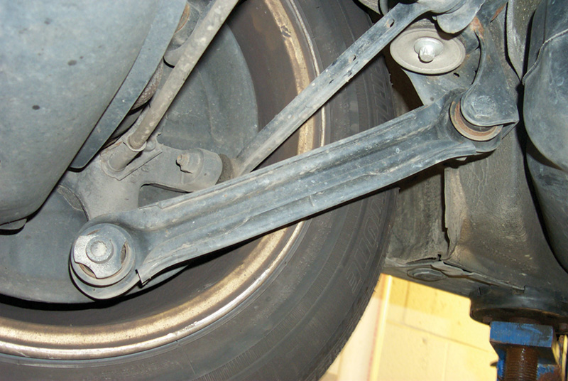
Tie Link
The shortest of the five links extends from an arm on the knuckle to a flange at the front of the rear subframe. This link controls the rear toe and thrust line. You make adjustments at the eccentric bushing at the front of the link.
Pushing link
Pushing Link
Running forward from the lowest part of the knuckle to the subframe, the pushing link transmits the drive forces from the knuckle forward to the body of the car. When the driver accelerates, the final, delivered engine torque applies to the vehicle mostly through the pushing link.
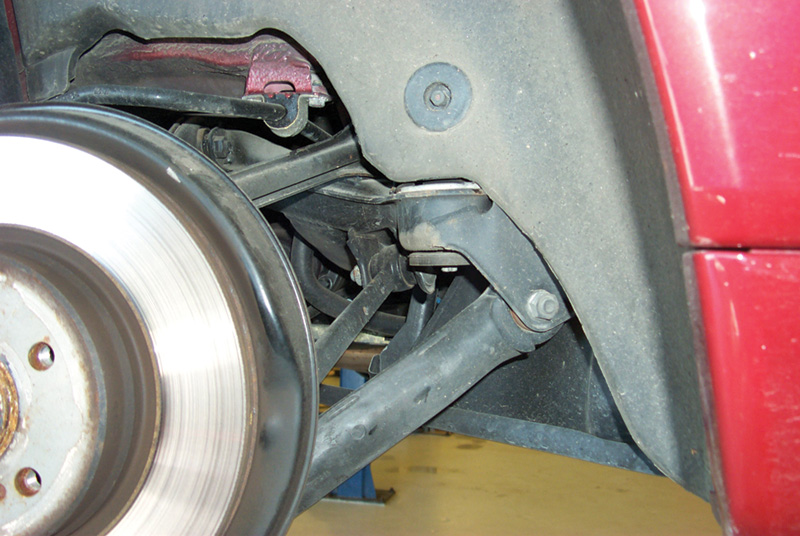
Pulling Link
Connecting the forward top part of the knuckle, immediately adjacent to the outboard end of the camber link, to the upper, forward part of the subframe, the pulling link transmits braking force as well as holding the knuckle vertically steady.
Swaybar link
Secondary Components
The swaybar and its bushings are above the drive axle but connect through the yoke at the outboard side of the spring link to the knuckle. Most Mercedes-Benz technical literature refers to the swaybar as a “torsion bar.†The driveshafts themselves are also, in a way, links between the differential and the wheels.
Front suspension
Front Suspension
Front suspension spring
The current Mercedes-Benz front suspension looks simpler than the rear, though there are several variations. All share a lower wishbone with the damper strut as far outboard as is compatible with clearing the wheel and tire. The springs are as far inboard as possible to reduce their share of the unsprung weight. You make the alignment adjustments through eccentric inboard bushings and at the tierod ends. The swaybar extends across the front of the suspension.
Certain models, beginning with the 140, use a small control arm at the top of the damper strut to better optimize caster and camber in certain driving modes. Some experienced mechanics find the angle of that small control arm is the quickest indication of any problem with suspension height, such as sagging springs. It pivots back as well as up in its normal travel, so once you’ve seen a few ‘known-good’s’ one that’s out of adjustment will leap out at you.
Alignment procedures
The linkage geometry may be complex, but adjustment procedures generally are not. You set caster and camber, front and rear, with the eccentrics (changing both at the same time!). Then you set the rear toe with the eccentric on the tie link, and once the thrust line is correct, set the front toe with the adjustable tierods.. If an eccentric adjustment can’t bring the system into specification, something is either worn beyond use or broken. Damaged struts are visible by comparison to the mirror-image strut on the other side; worn bushings will be visibly different from the others. Oil and heat damage should be evident to an experienced eye.
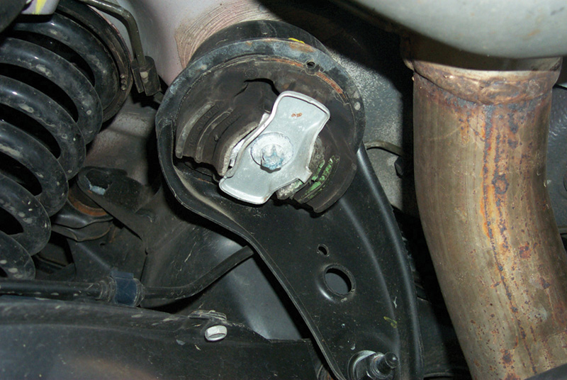
Subframe bushing
Subframes
The suspension does not support the body of the car directly. In each Mercedes-Benz, the suspension connects to a subframe through hard-rubber bushings, which in turn supports the body through other hard-rubber bushings. Much of the vehicles’ quiet running comes from this suspension and drivetrain bushing design. The engine and drivetrain also rest on the subframes on a third set of hard-rubber blocks, and this separation of the body from the suspension and drivetrain and their isolation from one another reduces the transmission of vibrations from the engine and from the road. Rubber and rubber/antifreeze bushings hold the major components at an effective, vibration-damping setoff. The antifreeze retains the advantages of liquid damping when temperatures fall below freezing.
The rear suspension shares the same indirect connection to the body through a bushed subframe. The rear subframe supports the body, but it also supports the differential with separate rubber bushings. The suspension links attach to the same subframe in several positions, as we’ll see below.
Critical as the subframes are, you should inspect them carefully for damage, especially for cracks, which can sometimes close up and hide when the weight is off the wheels. Rustproofing and accumulated dirt can conceal such cracks. Ball joints are subject to normal wear. Mercedes-Benz carries a simple go/no-go gauge to test them.
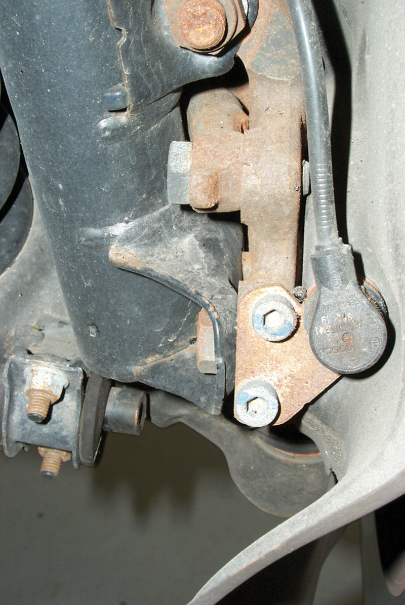
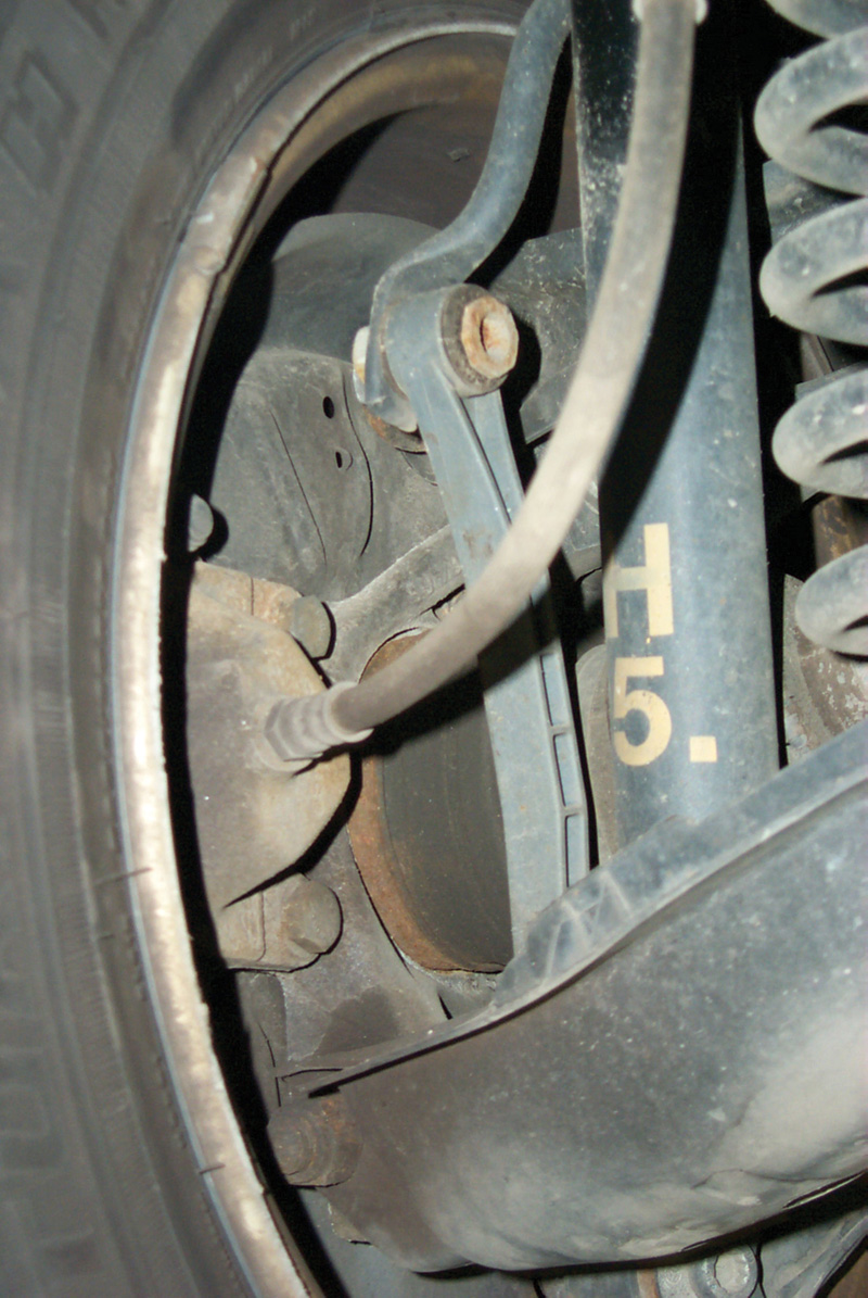
Wheelspeed sensor
Sometimes people decide to add their own ‘edge’ to the alignment specifications to give a car a particular ride, by tweaking the front camber and the like. This is not a particularly good idea with Mercedes-Benz cars. The company does a great deal of research in handling and suspension, and their German domestic customers expect the cars to drive in control even at high speeds and under challenging road conditions. Unless your customer weighs 400 pounds and always rides alone or is an anvil peddler with a trunk full of samples, you should probably stick with the book settings.
There are a large number of accessories that, on one model or the other, connect to different suspension links and components. Some are as familiar as ABS wheelspeed sensors; some are as unusual as the switch on the 129 (SL) rear linkage that triggers the roll bar up if the rear wheels leave the ground. Many Mercedes-Benz cars have different forms of active suspension (varying the shock damper rates), suspension height adjustment (some cars crouch down an inch or so closer to the highway for better aerodynamics at high speeds), sensors for locking differentials and more. If you find such a component in your way, determine what it is and how to remove it without causing unexpected problems later. In subsequent articles and issues, we’ll get to all the Mercedes-Benz vehicle systems, but for now we’re just looking at the multilink suspension basic geometry.
There are several other safety-related issues: Many Mercedes-Benz vehicles have diagonal cross-braces below the floor, particularly roadsters and convertibles. These function to keep the body stiff and square under driving stresses. Be sure you have the body supported equally and level at the designated jacking points before you remove these cross-braces. If not, there could be body damage in some other area of the car, and you may find it very difficult to get the cross-braces and their fastener bolts back into the right positions.
That applies to potential damage to the vehicle. This applies, in addition, to potential personal injury. Remember, only the damper struts hold the springs in place on these suspensions, when the car is on a lift and the suspension is at full extension. The front geometry vaguely resembles a MacPherson strut, but that’s not what it is. If you remove the damper strut without restraining the spring in a spring compressor, the spring can fly out of the seat with unexpectedly great force. Mercedes-Benz dealers carry spring compressors and model-specific end flanges that make this critical step safe and easy.
Finally, here’s a general precaution that doesn’t apply to vehicle or personal safety, but could make the difference between a satisfactory job and one you have to do over free. Multilink suspensions include a large number of bushings, at least one at either end of each link. Many of these links are clock-position specific, and many such specific clock positions are very easy to confuse with others for similar vehicles. For instance, suppose you’re replacing front control arm bushings on a 201 and using the clamping sleeve replacement bushing. On the forward front control arm bushing, the flat spots in the bushing go vertical [position for line drawing P33-2053-13] and the rear flats go horizontal, toward the center of the car. On a 124 or 129, however, you put the rubber flats vertical on the rear pivot of the control arm, and turn the front bushing flats horizontal toward the center of the car, just the opposite of what you do on the 201.
Now, nobody can remember all this accurately. That’s why we have reference materials and technical libraries. The point is, when you see a Mercedes-Benz bushing that is not perfectly symmetrical in every orientation, that means there is one correct and many incorrect ways to install it. Failing to find and observe that right orientation means the bushing will have a different and unpredictable elasticity than the engineers designed for that linkage pivot. The car will drive measurably worse than it did when new.
If you’ve worked on suspensions for any length of time, think of this as a reminder, not as nagging: When you’ve replaced a suspension bushing – any suspension bushing – lower the car’s weight onto the wheels so the bushing is under its normal rest load before you tighten the fastener (to the proper torque specification). This avoids giving the bushing an unintended twist, which can shorten its useful life as well as make it behave oddly. Bushings are the most important parts of any multilink suspension, and their correct assembly is the most important part of suspension work.Â


0 Comments