It’s been a decade since OBD II first hit the streets, so it’s definitely time to review your understanding
The Check Engine light, generically named the Malfunction Indicator Lamp (MIL) under SAE J-1930, is intended to be a red flag for the driver, but the fact that it’s illuminated is also important information for the technician. That is, providing he or she understands the basic strategies that make OBD II such a valuable diagnostic aid.
So, we’d better take a look at the big picture of OBD II’s logic — what actions is it intended to take when it detects a problem?
Essentials
To boil it down to essentials, the program will turn on the MIL if a system or component fails or deteriorates to the point where emissions could rise to one and one-half times the Federal Test Procedure standards. Of course, the conditions under which such a rise could occur have been determined through diligent research with real engines on dynamometers and on test tracks.
From an emissions standpoint, a misfire is about the most dangerous malfunction that can occur in a vehicle. Not only does it pump raw hydrocarbons out of the dead cylinder, but this extra fuel can cause the reaction inside the catalyst to become so hot that the cat either loses its ability to do its job, or actually melts down, perhaps clogging the exhaust system.
So, the instant the management software detects a misfire, it doesn’t just switch the MIL on, it flashes it once per second. The flashing stops only when the vehicle is being operated outside of the load and speed modes that could damage the cat. Even then, the MIL stays on steadily.
In fact, misfire is considered so important that on some models the software not only turns on the MIL when it detects this problem, but actually stops injecting fuel into the misfiring cylinder.
For most other tests, the OBD II management software won’t turn the MIL on until it sees two failures. That way, there won’t be numerous errors, hence motorist-irritating, warnings.
A trip or a cycle?
Before we get to the actual self-tests, we’d better explain what’s known as a “trip.” First, there’s “enable criteria,” which are the exact conditions the management software requires before it will run a particular self-diagnostic test.
So, a trip is a key-on cycle during which all the enable criteria for a particular test monitor are met, followed by turning the key off. This differs for each DTC.
More comprehensive than a single-monitor trip is the OBD II Drive Cycle—a set of driving conditions that satisfies the requirements of all OBD II monitoring sequences. The instructions on how to operate the vehicle to achieve the complete cycle are too detailed to include here, but we will say that a mix of accelerating, decelerating, idling, and steady-state cruising is required.
Don’t confuse trips or OBD II drive cycles with warm-up cycles, which the PCM counts to clear DTCs and freeze frames. A warm-up cycle is defined as a coolant temperature rise of at least 40 deg. F., reaching at least 160 deg., during which no new faults occur.
Multiple major monitors
Â
OBD II’s self-testing consists of seven major monitors, or eight if you count the oxygen sensor tests as two, plus a comprehensive component monitor, which is a catch-all for any emissions-control systems problems. The testing strategies used in each are interesting, and illustrate relationships among components that you may never have realized existed.
For the extremely important misfire monitor, the engineers looked at a number of different detection techniques, and settled on the acceleration and deceleration of the crankshaft during the combustion cycle (as you’d expect, it should slow down on the compression stroke, and speed up on the power stroke). The PCM monitors the acceleration and deceleration during combustion events and calculates a mean.
Through dynamometer research, the engineers found out that misfiring eight to ten percent of the time will damage the cat, so they labeled that percentage a “Type A” misfire. Then, they designed the system to keep track of misfires over a 200-revolution time frame — a buffer keeps the average. If the software sees no acceleration where there should be some, but sees deceleration instead, it registers a misfire immediately. The MIL will start flashing, and some systems will even cut fuel to that cylinder.
A “Type B” misfire isn’t quite so dangerous, but is bad enough to cause emissions to exceed one and a half times the standard. This is monitored over 1,000 revolutions by a different set of buffers. It doesn’t light the MIL the first time, but only on the second drive cycle. Typically, this is a one- to two- percent misfire. Note that misfire DTCs overwrite any other codes, and can only be removed with a scan tool.
How go the HEGOs?
OBD II runs two types of tests on HEGO (Heated Exhaust Gas Oxygen) sensors. One monitors the sensor’s activity, and the other checks the sensor’s electrical heating element. These tests are run only once per trip, and must be failed twice to illuminate the MIL.
An O2 sensor can fail the activity monitor for slow response rate, which is sometimes called a “big slope” for the way the wave looks on an oscilloscope. Or, it can fail for having too small a change in voltage output from rich to lean and vice versa.
A typical HEGO response test is done after the system achieves closed loop, and during steady state speed and load. The test forces fuel control changes at high frequency, switching rapidly between rich and lean. Can the HEGO respond to this high frequency, or has it become too sluggish and lazy? And, can it produce big enough voltage swings? If it can’t satisfy both standards, it fails.
Since any oxygen sensor is only accurate when it’s hot—at least 600 deg. F.—the HEGO heater monitor is intended to make sure the sensor is indeed properly heated. In a common approach, the heating element itself isn’t tested. Instead, the change in electrical resistance that the sensor’s output circuit experiences at various temperatures is watched.
After the ignition has been turned off, the PCM sends a five-volt signal to the sensor every 1.6 seconds. As the sensor cools down, its resistance increases, changing the voltage, which the PCM reads as temperature. Once the sensor is cool enough, the PCM commands a relay to complete the circuit to the heating element, then it watches as the sensor gets hotter and hotter. If it sees the proper voltage for several pulses, it passes the sensor.
Cat capacity
Obviously, the performance of the three-way catalytic converter is crucial to emissions control, and a cat’s efficiency is dependent upon its ability to store and release the oxygen needed to complete its reactions. If the engine’s air/fuel ratio is rich for too long, the oxygen stored in the catalyst can be used up. When this happens, the cat won’t be able to do its job of cleaning up the exhaust stream, and this situation is called catalyst “punch through.”
Since oxygen storage is related to catalyst performance, that’s what the catalyst monitor tests. The PCM compares the activity of the upstream HEGO to that of the one downstream. A good cat will have large oxygen storage capacity, so it will absorb fluctuations in the oxygen content of the exhaust, somewhat as an electrical capacitor smooths voltage variations.
So, the PCM expects to see a big difference between the amount of voltage change activity—actually, the number of rich/lean switches per unit of time—in the upstream O2 sensor and the downstream O2 sensor. If, instead, it sees that the ratio between the two is close to one, the catalyst fails its monitor.
Evap mishap?
The evaporative system monitor watches for leaks that could allow raw gasoline fumes to escape into the atmosphere. Originally, it was required to identify a leak equal to what could pass through an orifice .040 in. in diameter, but that’s now down to .020 in.
In a typical version of this monitor, the PCM shuts off the charcoal canister vent solenoid and opens the purge solenoid at steady-state cruise. This allows manifold vacuum to affect the pressure in the fuel tank, which is read by a pressure transducer. It maintains this condition until the pressure drops to a specific value, then it closes both solenoids to see if this vacuum holds for 10-20 seconds. No? Then the evap system fails, and a pending code is registered. Two failures in a row and a DTC is set and the MIL is turned on.
Common DTCs are P0442 (small leak) and P0455 (large leak), which tell you that the evaporative emissions monitor has detected a gasoline vapor leak. Commonly, this is set because the gas cap wasn’t screwed on completely after refueling, or that the cap itself is faulty. On some late-model BMWs, however, there was a problem in the filler pipe itself that caused a failure of this monitor, and replacing the cap or advising the customer to make sure he or she tightens it completely wouldn’t head off a reoccurrence.
Recirculation examination
OBD II regulations state that EGR must be monitored for abnormally low or high flow rates, which can dramatically increase the production of NOx. In one common approach to accomplishing this test goal, the principle applied is that the position of the EGR valve pintle will have a direct effect on manifold pressure, as read by the MAP sensor. In other words, opening the EGR valve decreases manifold vacuum, and vice versa.
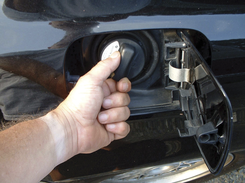
DTC P0442 or P0455 may be set most often because somebody didn’t install the gas cap properly, but don’t automatically jump to that conclusion because real system leaks are also a possibility.
To test EGR flow, the PCM forces the valve open during closed-throttle deceleration, or forces it closed during a steady-state cruise, depending on the model. The management software then compares MAP sensor readings over several valve actuations and calculates EGR flow. If this is out of range, the system fails the first test of the two in a row it will take to set a DTC and illuminate the MIL.
Pumped air and fuel trim
Secondary air is what’s injected into the exhaust stream during open loop operation to help oxidize HC and CO, so it obviously affects emissions. While this system isn’t used on as many new cars as it once was, where it is present OBD II regulations say it must be monitored. A typical testing procedure simply has to determine that the system is indeed capable of injecting air. To do this, the management software first determines that the HEGO has reached operating temperature, then reads its signal to make sure it indicates the lean signal air injection causes.
The fuel monitor is one of the most important in OBD II, so it’s fortunate that it’s also one of the easiest to understand. The diagnostic software simply keeps track of the dynamic adjustments in fuel calibrations known as long-term and short-term fuel trim. If these exceed certain specifications in the same direction—in other words, both making lean corrections or both making rich corrections—it identifies a problem, such as faulty fuel pressure, clogged injectors, a vacuum leak, etc., and the fuel system fails its test.
Traditional self-diagnostics
Finally, there’s the comprehensive component monitor, which looks at emissions-related factors that aren’t tested by previously-mentioned specific monitors. Many of these are checked in the same way as they have been by the car companies’ proprietary self-diagnostics since the early ’80s. This monitoring is continuous, so no enabling criteria are needed.
First, there’s the integrity of the electrical circuits that are involved in the emissions control system, both for sensors, such as those for coolant and intake air temperature, and actuators, such as the idle air control motor or the canister purge solenoid. Is there an open, or is there a short to ground or battery voltage? If so, a code is set and the MIL is illuminated.
Second, there’s input rationality. In other words, do the signals from the sensors make sense when compared to other inputs and PROM information. If, for example, the engine has been running for half an hour, yet the coolant temperature sensor is sending a signal that represents a below-zero reading, there’s obviously a discrepancy, so a code is set and the MIL is turned on.
Finally, there’s functionality. Are the PCM’s commands being carried out? For instance, when the IAC motor is told to go to a specific position, does the rpm signal match? No? Then it’s time to set a code and warn the driver with the MIL.
We’d better expend some space explaining the OBD II DTCs. These follow SAE standard J2012, which requires a five-character alphanumeric code. The first character is called the prefix letter, and it may be a “P” for powertrain, a “B” for body, or a “C” for chassis. Only “P” codes are OBD II-related because they have an effect on the vehicle’s emissions.
If the second character is a zero, it tells you the DTC is a standardized SAE code. If it were a one, it would be a trouble code that is part of the car maker’s proprietary diagnostics, and to interpret it you would need that company’s factory information.
The third character of a “powertrain” DTC indicates the system the trouble is in. The numeral 1 stands for fuel and air metering, 2 the fuel injector circuit, 3 the ignition system or misfire, 4 auxiliary emission controls, 5 vehicle speed control and idle control system, 6 computer output circuits, 7 and 8 the transmission.
The fourth and fifth characters identify the specific trouble the system has detected.
Put out the light and clear the code
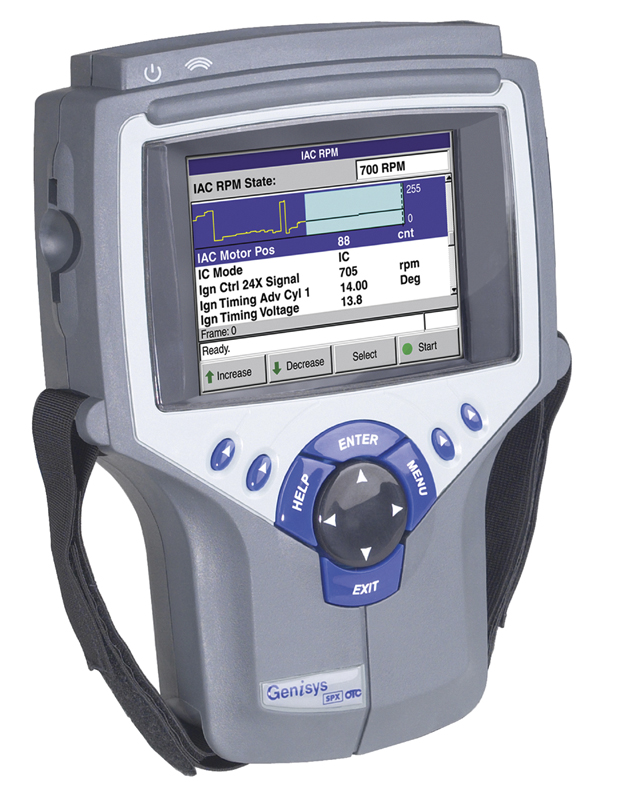
Before you buy a generic scan tool for Global OBD II, make sure you know exactly what it’ll work on.
After you’ve fixed the problem, you’re still not done until you’ve cleared the code and made the MIL go out, which is easily done with your scan tool by selecting the “Clear Info” command. Otherwise, it will take 40 warm-up cycles for the system to automatically clear.
What about just disconnecting the battery or pulling the computer’s fuse to erase the memory, the way it’s been done for years? Well, believe it or not, some computers can retain their memory for months without battery power, so this just isn’t practical anymore.
Finally . . .
Let’s face it: It’s not so easy to fix cars anymore. Sure, the skills you might have learned in the past will make it possible for you to replace a water pump, take care of a steering or suspension problem, bolt on a new alternator or starter, reline the brakes, or do many other jobs. But when it comes to a problem that involves driveability, performance, or emissions, it’s a whole new world of complexity and sophistication.
But the technician hasn’t been entirely forgotten in all this upheaval. One of the main goals of OBD II was to simplify diagnosis of the systems that are part of electronic engine management. The more you work with OBD II cars and your scan tool, the more you’ll learn about putting this system to work for you where it counts: Helping your customers with efficient, accurate diagnosis.
In future issues of TECHDRIVE, we’ll cover some very specific ways in which those clever engineers at BMW have actually put the OBD II concept into practice. Even though one of the basic reasons it exists is to give the aftermarket a generic diagnostic system, there’s a certain amount of leeway in the regulations on how each carmaker can best achieve that goal given its particular engines, EFI, emissions controls, etc.
|
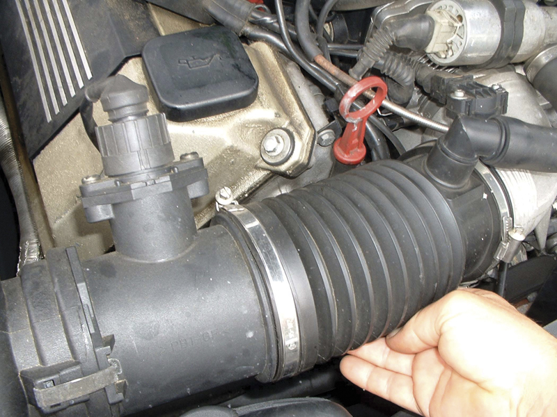
We fondly remember our first encounter with this situation. A 7 Series BMW was being driven into the bay next to ours, and it was running badly — made us think of an old carbureted car with a huge vacuum leak, say from a disconnected brake booster hose. |
Â


0 Comments