It’s been exactly 30 years since this almost magical component hit the streets, so it’s definitely time for a review of diagnosis and replacement options. After all, there’s more than one way to skin a cat
Catalytic converters have been in almost universal use since 1975, so you may think of the topic as old hat. But the advent of sophisticated second generation on-board diagnostics systems (OBD II) coupled with state-mandated emissions testing has led to increasing focus on converter efficiency. That means troubleshooting has risen to a new level of complication.
For reasons perhaps better left unexamined, the old saw has it that there is more than one way to skin a cat. This article offers a few modern ways to test a cat.
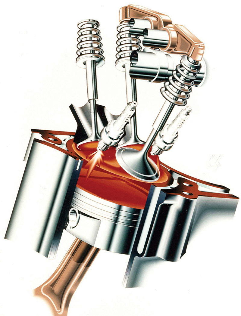
No matter how sophisticated the design of a combustion chamber, such as that of this three-valve, two-plug Mercedes-Benz V6, and of the engine management system involved, downstream cleaning is still required.
Converter Basics
We’d better begin with converter terminology. All modern cats are monolithic, which means they have a microscopically thin coating of catalytic elements on a ceramic honeycomb called a substrate.  Early cats were of the oxidation type. Since all they did was promote the burning of HC and CO, they’re often called two way converters.Â
A variation on this theme is the “light-off” or “pre-cat,” a small oxidation unit installed within six inches of the exhaust manifold so that it gets hot enough to start working quickly, which helps the car meet emissions standards during the difficult warm-up period.
With the introduction of closed loop electronic engine management systems, which first appeared in the late ’70s, we got the reduction or three way catalyst (TWC), so named because it not only handles HC and CO, but also reduces NOx compounds to harmless nitrogen and carbon dioxide. A three way unit has the reduction section upstream of the oxidation section.
Even the most efficient engines cannot achieve perfectly clean combustion. Partly, this is the result of the nature of commercial gasoline, which is a soup made of the many compounds within crude oil with boiling points ranging from about 50° to 200° C (120-400º F). These are primarily hydrocarbons, but may also include a smattering of contaminants, including sulfur compounds. Refiners mix in a variety of detergents, surfactants, and other additives, too.
Engine operating parameters also vary widely through a broad range of temperature and load conditions, necessitating corresponding deviations from stoichiometry, the “ideal†14.7 to one air/fuel ratio (by weight,of course), which is represented by the Greek letter lambda in engineering jargon.
Thus, the net products of the internal combustion engine may include significant concentrations of unburned hydrocarbons (HC), partially burned hydrocarbons in the form of carbon monoxide (CO), and various oxides of nitrogen (NOx), all in addition to the main exhaust components of nitrogen (N2), water (H2O), and carbon dioxide (CO2).
By just being present during the reduction and oxidation reactions that occur inside the converter, the thin layer of “noble metals” on the ceramic substrate vastly reduce the amount of NOx, HC and CO a car spews into our precious atmosphere without being changed one whit in the process. That is, if everything upstream is working properly, which we’ll explain later.
To accomplish this important task, the catalytic converter relies on a series of three basic chemical reactions.Â
The first, performed in the reduction bed, strips excess oxygen atoms away from NOx compounds, returning the nitrogen to its natural state. The simplified equation for this process is
NOx + CO —> N2 + CO2 .
This reaction relies on the presence of a small amount of CO in the exhaust stream to accept the oxygen atoms removed from the NOx. Oxides of nitrogen first arise when combustion chamber temperatures exceed the ignition point of nitrogen, which is about 1,370° C (2,500º F.). These extreme temperatures occur mostly under high-load conditions and are greatly exacerbated by lean air/fuel ratios. However, the CO needed to complete the reduction reaction is indicative of a rich air/fuel ratio. The need for a recurring regular supply of CO to reduce NOx levels is a key reason for the normal oscillation between rich and lean mixtures associated with a properly-operating feedback/closed-loop engine management system.
The second and third chemical reactions take place in the oxidation bed of the converter. There, the HC and CO in the exhaust are burned (combined with oxygen) as indicated in the following chemical reactions:
 HC + O2 –> H2O + CO2 and CO + O2 –> CO2.Â
Obviously, both of these reactions require the presence of substantial quantities of oxygen (O2). So, where does this oxygen come from, and how is it made available.
You’ll recall that O2 is a reliable indicator of a lean condition, while CO marks its opposite. This, then, is another reason for the mixture oscillation mentioned previously. The oxygen used in the converter’s second bed passes through the engine during periods of lean operation and is sequestered within the ceramic substrate to be used when needed to clean up the byproducts of rich running. This is sometimes supplemented by a secondary air injection system, which used to be called a “smog pump,” and has the same effect as a blacksmith’s bellows
Catalytic converters work when the basic mixture is close to stoichiometry, and efficiency is best when lambda falls in a range of 0.97 to 1.03, which represents an air/fuel ratio of 14.26:1 to 15.14:1. The catalyst does a much poorer job of cleaning the exhaust when lambda falls outside that range, indicating a mixture that is too rich or too lean.
Now that we know what the converter does, and why it requires a mixture that swings between rich and lean to operate properly, we’ll look at some converter tests that can help us differentiate between good and bad cats.
Testing Oxygen Storage
 As we’ve seen, one of the converter’s most important jobs is oxygen storage, so it makes sense to test that if we can. The oxygen storage test is relatively simple and can be done with a four-gas analyzer and minimal additional equipment.
Start by warming the engine to normal operating temperature. You want the catalytic converter to reach its operating temperature threshold as well, so you may have to drive the vehicle or operate it above idle for a few minutes (catalytic converters require a minimum internal temperature of around 230° C, or 450º F., before they “light offâ€).
Next, insert the analyzer probe into the tailpipe and hold the engine speed constant at about 1,500-2,000 rpm. Watch the analyzer’s O2 reading. When it drops to zero, briefly snap the throttle open and monitor the O2 reading just as CO first begins to rise. If the O2 exceeds 1.2% at this time, the converter fails this test.
If the oxygen readings never reached zero, you may have to repeat the procedure, this time adding propane through the air filter until you deplete all the oxygen stored in the converter. In essence, what you are doing in this test is using up all the stored oxygen, then, with the large gulp of air from the throttle snap, refilling the converter.
Obviously, oxygen storage is only one aspect of converter function, although it is considered important enough to be the basis of OBD II self-testing.Â
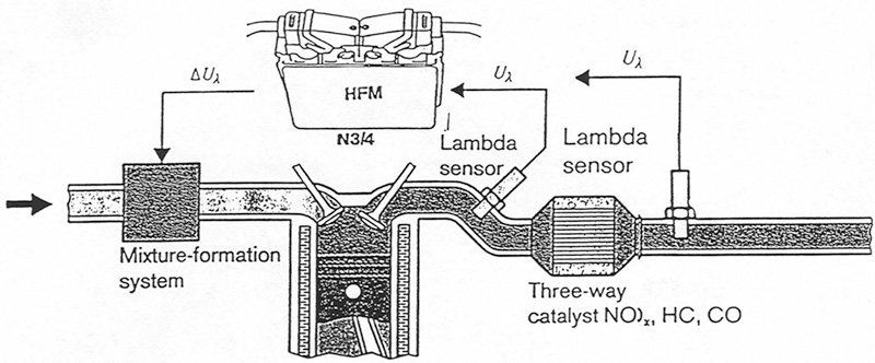
With OBD II, the signals from the upstream and downstream oxygen sensors are compared to determine whether or not the cat has sufficient oxygen storage capability.
Burning HC?
A related test measures the converter’s ability to actually oxidize hydrocarbons efficiently, and is called, logically enough, the oxidation efficiency test. You should carefully review the procedure and locate all necessary connectors and tools before you begin, so please read through the entire sequence before starting. This test must be performed in a short period of time to be accurate, so you need to understand all the steps before you start.
- Run the engine and your gas analyzer until both reach normal operating temperature.
- Hold the engine at about 2,000 rpm for at least two minutes to warm the catalytic converter to its operating temperature.
- Turn the engine OFF.
Note:Â You must complete the test within five minutes after turning off the engine or the catalyst will cool too much to work.
- Disable the fuel and ignition systems.
- Attach a battery charger and crank the engine at wide-open throttle for at least 10 seconds to clear all the fuel from the intake and exhaust.
- Attach a propane source to a large, centrally-located vacuum line (PCV or brake booster).
- Insert the analyzer’s exhaust gas probe at least 12 inches into the tailpipe.
- Open the propane source valve and crank the engine for 15 seconds with the throttle closed.
- Read and Record peak HC and CO2.
The test standards are as follows:
If HC is: ppm then CO2 should be greater than: %
|
550 ppm |
1.7% | Â | 750 ppm | 2.5% | Â | 1,000 ppm | Â 2.9% |
|
1,250 ppm |
3.8% |
 |
1,500 ppm | 4.8% | Â |
1,750 ppm |
5.4% |
| 2,000 ppm | 6.2% | Â | 2,250 ppm | 7.0% | Â | Â | Â |
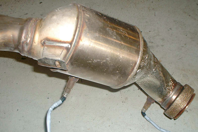
Here, you can see the positions of the upstream and downstream oxygen sensors required by OBD II. This is from a late-model Mercedes-Benz V12.
Remember, these are the minimum CO2 figures – the more the merrier! If your HC readings fell outside of the minimum and maximum figures in the left column, you’ll have to perform the test again, starting from the top and adding more or less propane as required. A little experience will help you adapt the test to your equipment.
What can we learn from this test? It tells us how much of a given amount of fuel can be oxidized by the hot catalyst.Â
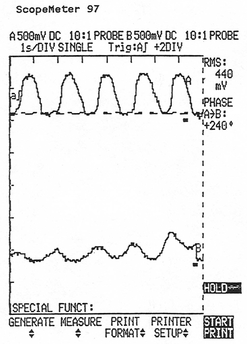
OBD II decides whether or not a cat is capable of storing enough oxygen to do its job by comparing the signal from the upstream oxygen sensor to that of the downstream sensor. This lab scope screen shows the upstream O2 sensor signal (top) and that of the downstream sensor simultaneously. There’s too much activity in the downstream unit, indicating that the catalyst isn’t operating at optimum efficiency.
OBD II Considerations
Of course, vehicles equipped with OBD II systems (mandated for all ’96 and up models) perform an ongoing self-test of catalyst efficiency by monitoring the voltage of the downstream oxygen sensor(s). Since O2S voltage varies inversely with exhaust oxygen content, the PCM essentially performs a catalyst oxygen storage test similar to the one described above. Mercedes-Benz uses a complex algorithm comparing the upstream and downstream oxygen sensor signals to determine if it should set a code.
The most common codes for a failed converter are P0422 and P0432, signaling converter efficiency below the specified threshold for banks one and two, respectively, on a V6, V8, or V12.Â
So, should you trust that each instance of an OBD II converter fault code in fact indicates that the converter has failed? Tempting though it might seem to jump to such a conclusion, further testing is usually indicated. Here’s why: A number of related faults can cause the PCM to conclude that the converter is faulty, when, in fact, the problem lies elsewhere.Â
The most common cause of a “false†converter DTC is a slight misfire, just below the misfire monitor’s reporting threshold. Since a misfire results in additional oxygen being pumped into the exhaust stream, the converter’s oxygen storage capacity may soon be exceeded. The resulting drop in downstream O2S voltage may be misinterpreted as a converter fault, so the PCM sets a code.
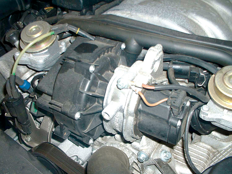
Problems in the secondary air injection system can set codes that may make you believe the catalyst itself is bad when it’s really working fine. Always make sure of where the problem lies before replacing expensive components, such as an O.E. cat.
Another potential cause of a false DTC is a slight leak in the SAS (Secondary Air Injection System). If the PCM detects such a leak, it will normally set a pending code, subject to confirmation, and will suspend monitoring of the catalyst efficiency to avoid setting a false converter DTC. Occasionally, however, an as-yet undetected intermittent fault in the SAS may result in a false condemnation of the converter’s efficiency. Any exhaust leak downstream of the front O2S can, in fact, cause a false converter efficiency DTC.
For these reasons, it’s a good idea to perform at least one of the tests outlined above to verify any converter DTC before replacement.Â
Cat Killers
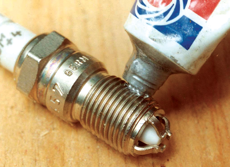
Just the simple, logical maintenance step of replacing spark plugs at reasonable intervals can prevent misfires that may cause cat problems.
Ideally, catalytic converters should last as long as the vehicle on which they were originally installed. If you’re forced to change one, ask yourself what went wrong with the original before you bolt on a new unit. Catalysts that die young do so from contamination and damage caused by overheating. Common sources of contamination include engine oil, antifreeze, and silicone sealers that are not rated catalyst safe. Contaminants coat the catalyst’s reactive material, reducing chemical action and catalyst efficiency.
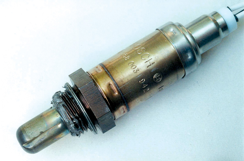
For many years, it’s been the opinion of diagnosticians that a dead or lazy oxygen sensor is a common destroyer of catalytic converters.
As already mentioned, a catalyst is a compound that hastens or facilitates a chemical reaction, but is not consumed in the process. The catalytic materials in a standard converter include rhodium, platinum, and palladium. Unfortunately, these expensive materials all degrade in the presence of sulfur-bearing compounds. Thus, using high-sulfur fuels may, over time, damage the catalytic elements and reduce the converter’s efficiency. Additionally, high-sulfur fuels can diminish oxygen sensor speed and accuracy. The resulting mixture inaccuracies may then tax an already degraded catalyst beyond its limits.Â
Overly rich conditions and engine misfires pump more CO and HC into the cat than it can handle. This increases chemical activity and heat to a point where the catalyst suffers a meltdown. Never replace a catalyst without locating and correcting the conditions that destroyed it in the first place. If you do find that the converter has fallen into sub-par performance, your next step should be to determine the exact cause of the failure.Â
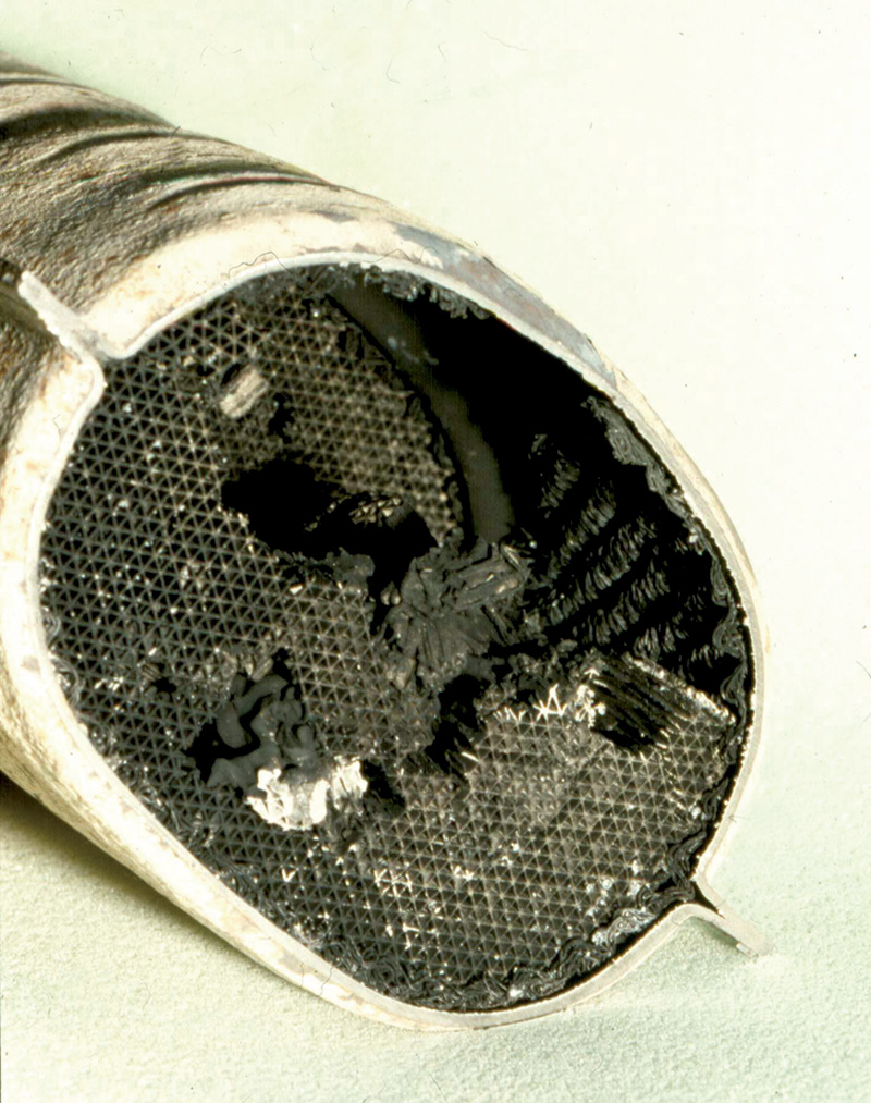
A chronic rich condition combined with sufficient oxygen can overheat a catalyst to the extent of a meltdown that results in flow restriction and a serious loss of power. This one is from the pre-O2-sensor K-Jetronic era, but it can still happen today.
Other Failure Modes
In addition to losing oxidation efficiency, catalytic converters can fail by losing reduction bed efficiency as well, or by becoming partially or wholly plugged. The loss of reduction bed capacity often results from melting caused by excessive temperatures due to misfire. It may also result from prolonged lean operation, most commonly associated with a faulty mass air flow sensor unit.
Plugging is usually associated with prolonged overheating. Catalytic converters will work as hard as they can. In fact, they’ll work themselves to death if you let them. This condition is most easily detected during a routine manifold vacuum snap-throttle test, or by installing a back-pressure gauge into the exhaust system, perhaps at the upstream O2 sensor port.
Replacement Considerations
Remember that the original converter was designed and engineered to last for the lifetime of the car. The O.E. converter achieved a 70% to 97% efficiency in the reduction bed, and an even higher efficiency in the oxidation beds. On the other hand, aftermarket converters for Federal spec cars need only certify a minimum reduction bed efficiency of 30%, while even CARB-certified (California spec) replacements need only test at a minimum of 60% or 70% efficiency, depending on the application.
You’ve probably also seen aftermarket catalytic converters whose volume is only a fraction of the originals they are specified to replace. Experience has shown that while many of these undersized converters initially function superbly as oxidation catalysts, their small size results in a quick performance degradation and early failure. Additionally, reduction bed performance is usually extremely limited in efficiency and longevity.
Thus, opting for an aftermarket replacement may be a false economy because your customer will be seriously disappointed with you, especially if the car fails its next state emissions test. Where cost considerations preclude purchasing a new original equipment converter, a refurbished unit may be available.
Of course, all this is moot if the vehicle is still under the federally-mandated emissions warranty. Naturally, a cat is considered a major emissions-control component, so is covered for eight years or 80,000 miles. That means if the car is a ’98 or up and has less than 80K on the odometer, you should send your patron back to the car dealership. Providing the vehicle hasn’t been abused and has been properly maintained, the automaker is responsible for all costs associated with catalytic converter replacement.
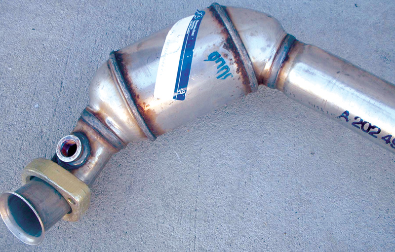
It’s not too likely that an aftermarket cat would either fulfill the job performance-wise, or be practical to install. So, if one of your customers has failed his or her emissions test because of poor catalytic converter performance, an O.E. replacement is probably the right answer, no matter how expensive.
Â


0 Comments