Oxygen sensors are evolving, as is borne out by the introduction of the wide-band type. Yet there are still many, many older style units out there in the real world for you to deal with. Here’s everything you have to know from construction and operating principles to diagnosis and service.
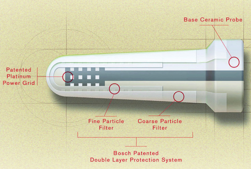
Although all oxygen sensors are carefully constructed so that harmful particles don’t get through to the platinum-coated zirconium, contamination is still the biggest killer.
Other pages in this issue of StarTuned will give you a solid understanding of the recently-introduced wide-band oxygen sensor, which amounts to a big improvement where emissions reduction and enhanced engine performance is concerned. But at least 90% of the cars you work on are not so equipped — we all know that Mercedes-Benz owners tend to keep their cars for years and years, and we often see specimens with over a quarter of a million miles on them. So, it’s important that you also have a deep and comfortable understanding of previous oxygen sensor technology, failure modes, troubleshooting and replacement procedures. Hence, this article.
We remember being intrigued and astonished three decades ago when the oxygen sensor first appeared as the cornerstone of the Bosch Lambda-Sond system. The industry was just becoming accustomed to electronic ignition, and this step up into closed-loop engine management was staggering. It knocked the service business for a loop, and some of us haven’t fully recovered yet. The motoring public, of course, is still blithely unaware of the whole concept — customers are commonly shocked to hear that their cars have a computer aboard, or that there’s such a thing as a sensor that gives it input on the air/fuel mix. Mercedes-Benz was one of the first carmakers to adopt this concept as a means of staying at the forefront of engine efficiency and emissions control, so you might see examples nearly 30 years old in the bays of your shop.
Besides being amazed at the idea of on-board exhaust analysis by means of what’s variously called an oxygen, O2, EGO, HEGO sensor, or Lambda probe, we were dubious at the time about the potential longevity of a sensitive component located in that horrendous blast of hot gases. How long could it possibly last?
That fear proved unfounded. Early on, replacement was recommended every 15,000 or 30,000 miles. Experience has shown that many specimens are still fine, thank you, after several times that, and regular retirement intervals were lengthened to 60,000, then eliminated altogether. “Many” is the key word, though. Lots of them do indeed die prematurely from causes that have nothing to do with the quality of their manufacture.
A study conducted for CARB (California Air Resources Board) many years ago stated that 70% of fuel injected vehicles that fail the state’s emissions test have bad O2 sensors. Also, a faulty one can cause fuel economy to decline by 10-15%, costing a less heedful motorist maybe several hundred dollars a year, and perhaps melting down the cat in the process. While this situation has improved in the period since the study, it hasn’t been eliminated.
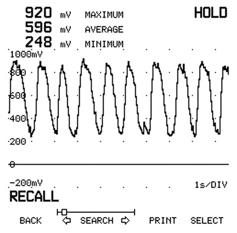
With a lab scope, you can easily see what kind of a signal the oxygen sensor is sending. This is obviously a good one — the pattern is perfectly normal.
Platinum-coated zirconium
Not counting the wide-band type, there are really two basic varieties of mixture monitors, zirconium and titanium. Introduced in 1986, the latter is found only in a small percentage of the vehicles on the road, none of them from Mercedes-Benz, so we’ll concentrate on the former here.
A basic zirconium oxygen sensor comprises a steel housing with a hex and threads, a louvered shield over the tip, and a hollow cone-shaped internal element made of zirconium dioxide (ZrO2, a ceramic material) called a “thimble,” which is coated inside and out with a thin layer of micro porous platinum. The outer layer is exposed to the exhaust stream, while the inner layer is vented to the atmosphere and attached to a wire that runs to the PCM (Powertrain Control Module).
It’s actually a galvanic cell — think of a flashlight battery. The zirconium dioxide acts as the electrolyte, and the platinum layers serve as electrodes. Once the ZrO2 reaches about 600 deg. F. (over 300 deg. C.), it becomes electrically conductive and attracts negatively charged ions of oxygen. These ions collect on the inner and outer platinum surfaces. Naturally, there’s more oxygen in plain air than in exhaust, so the inner electrode will always collect more ions than the outer electrode, and this causes a voltage potential.  Electrons will flow.
The concentration of oxygen in the exhaust stream determines the number of ions on the outer electrode, hence the amount of voltage produced. If the engine is running rich, little oxygen will be present in the exhaust, few ions will attach to the outer electrode, and voltage output will be relatively high. In a lean situation, more oxygen will be present, and that translates into more ions on the outer electrode, a smaller electrical potential, and less voltage. Here’s a helpful memory trick: just remember “L=L” for Lean=Low.
The voltage is always small, never exceeding 1.3 volts (or, 1,300 mV) or so, with a typical operating range being between 100 and 900 mV. But it’s enough for the computer to read. If it receives a sensor signal of less than about 450 mV, it recognizes a lean condition, and if it gets more than that amount of voltage, it registers a rich condition (it’s one or the other, there’s no in-between). Either way, it instantly corrects by adjusting the injection pulse width.
You may have heard the term “dithering” applied to O2 sensors. The dictionary will tell you that a “dither” is a state of agitation or indecision. As a verb, it’s a pretty good description of how this sensor’s signal is supposed to be continuously switching from rich to lean and back.
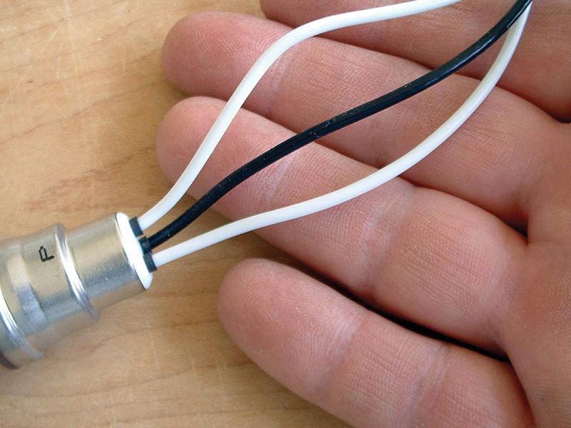
Typically, the wire that carries the voltage signal to the PCM is black. The others here are current feed for the internal heating element and ground.
No heat, no go
Remember the 600 deg. F. temperature mentioned above? Good, because it’s important. Oxygen sensors simply will not produce voltage until they’re hot, and many perfectly good units have been replaced because some technicians test them when the engine is first started, or after it’s idled for a while, which allows the old one-wire unheated type to cool off. That’s one reason the planar type is superior — it heats up fast.
With a cold sensor, the computer realizes it’s not getting a signal and will operate in open loop, holding the mixture at a fixed setting. Since good fuel efficiency and minimum exhaust emissions can only be had during closed loop, it’s desirable to get the sensor hot as soon as possible after the engine is started, and to keep it there while idling, so all late model thimble-type oxygen sensors are equipped with an electrical heating element, not to mention the rapid heating capabilities of the planar type.
Wires
While your basic first-generation sensor will have one wire, you’ll also see specimens with two, three, or four. In most cases, two means it’s an ordinary unheated unit. The extra wire just provides a more dependable ground than thread contact in the manifold or head pipe. Three leads indicate a HEGO (Heated Exhaust Gas Oxygen, one for the signal, two for the heater circuit) sensor. Although the signal wire is typically black, it can be hard to tell which of the other two is ground and which is juice to the heating element, so a wiring diagram would be helpful. The fourth wire? Simply a dedicated ground for the signal portion.
Numerous
If all zirconium oxygen sensors work in pretty much the same way, why are there so many part numbers? To begin with, the replacement should have the right number of wires, as just mentioned. So there you have four right off, but it actually works out to more than that because of the different styles of pigtail connectors used in their harnesses of various models.
But there are other, more subtle considerations. For instance, there’s the spacing of the louvers in the business end. Most common is the wide-slot type, but there’s the narrow-slot variety, too. In unheated sensors, its purpose is to protect the ceramic from thermal shock in applications that put the sensor close to the exhaust ports by making it heat up more gradually. If you were to install a narrow-slot unit in a car that requires the wide-slot type, it would take a long time to heat up to operating temperature, and may keep throwing the car into open loop at idle because it’s not staying hot enough to work. There’s really no problem using a wide-slot in a narrow-slot application, however. With heated units, the situation is reversed. Narrow slots are used to keep the sensor from cooling off. All this is more evidence in the case for purchasing O.E. genuine parts.
A mention of the waterproof feature is appropriate here. All it means is that the reference air isn’t picked up through a vent right at the sensor itself where water and other contaminants are plentiful. Instead, there’s a sealed sleeve of insulation that runs up into the harness, or even all the way to the PCM, before it opens to the atmosphere. Since only a tiny amount of reference air is needed, enough will flow between the gaps in the stranded wires inside the insulation. You can get into trouble if you solder these cables because it wouldn’t take much flux, solder, or melted plastic to block those essential gaps.
Substance abuse
Several things can wreck an oxygen sensor. Mechanical damage in the form of a broken element or wire certainly happens, but the most common killer is contamination. Lead, carbon, metals from motor oil additives, and silica (from high-volatile RTV silicone sealants or antifreeze – expect O2 sensor problems whenever you replace a blown head gasket) in the exhaust can all coat that precious platinum and make the unit sluggish or altogether inoperative. There have even been cases of sensor poisoning from gasoline with a high silicon content, 500 ppm when 4 ppm is enough to cause trouble. By the way, silica (SiO2) appears as a fine white powder on the shield.
Deposits on the exhaust-side electrode increase voltage output, giving a false rich signal. This drives the system lean. But these coatings aren’t always the kiss of death. Try running the engine at 3,000 rpm for a few minutes, or take a drive, then retest. You may have burned off whatever was interfering with juice generation. On the other hand, if silica or metal deposits get hot enough, they’ll melt into a coating that can never be removed.
The most common oxygen sensor failure is gradual degradation. Over time, sensors slow down in frequency and lose amplitude. Prior to OBD II, computers did a poor job of self-diagnosing this. A scan tool is not very good for diagnosing a degraded sensor unless it has graphing capability, and even then it can be limited by the data transmission rate of the computer. Additionally, no scan tool that we’ve seen shows negative numbers when a negative-biased O2 sensor switches below zero volts.
For many highly-skilled diagnosticians, the lab scope (a.k.a. digital storage oscilloscope, or DSO) is the tool of choice for oxy sensor testing. In California, the DSO is required for emissions inspection and repair stations. OBD II testing of oxygen sensors includes a test for the speed of rich-to-lean transition as well as lean-to-rich and amplitude. The same test can be conducted with a lab scope.
The California BAR (Bureau of Auto Repair) – recommended procedure is as follows:
- Monitor O2 sensor operation and insure closed loop.
- Feed propane to engine at a slow rate and wait until computer adaptive strategy restores O2 switching.
- Cut propane off (O2 sensor will swing lean).
- At this point, goose the throttle to feed an enrichment command.
- Press “Hold†on the scope to capture the lean-to-rich transition, and measure the response time with scope cursors.
A fresh sensor will be able to make the transition in under 100ms and should be able to clear 800 mV on the rich side and drop below 175 mV on the lean side when the propane is first shut off.
The rich-to-lean transition is measured similarly except that a quick large vacuum leak after the mixture has been forced rich is used to get the swing to lean. If you’re fast or have a recording lab scope, you can get both readings with the same test.
One thing that has proved to be abundantly true is that oxygen sensors do not survive well on a diet of coolant. Techs have told us they’ve been burned on head gasket replacement jobs that came back with a MIL (Malfunction Indicator Lamp) on, a dead oxygen sensor, and a typical customer comment, “It never did that beforeâ€. The techs were left to choose between two undesirable options: Installing the sensor and eating the cost, or trying to explain to the customer that the blown head gasket had killed the sensor. Customers who have just spent a large amount of money for a head gasket job are not usually very happy about springing for another bill. The moral of the story is to remember to write the cost of the oxygen sensor(s) into your repair estimate for head gasket replacement.
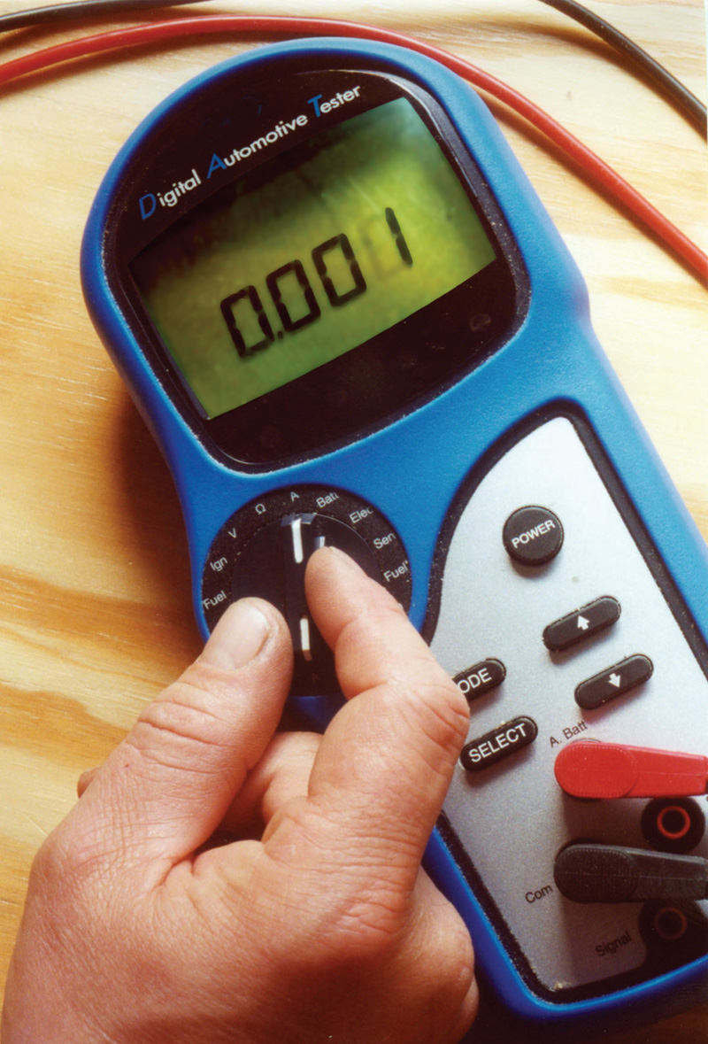
Your DMM should have a voltage bar scale to make it useful in checking oxygen sensor output, but a graphing multi-meter, or even a lab scope, would give you better information.
For some reason, most people have never even considered the possibility of contamination of the electrode on the reference air side, but it’s a problem nevertheless. Typically, it comes from the smoke given off during the deterioration of silicone rubber seals or insulation, or from aerosol wire-drying chemicals, cleaners, etc. used under the hood. Blocking the reference air lowers the unit’s voltage potential, making it send a false lean signal that drives the mixture rich, possibly cooking the catalyst.
Likely complaints
Symptoms of a lazy or dead oxygen sensor are surging, hesitation, poor overall performance, lousy gas mileage, and a rough or rolling idle (all with a warm engine — never blame the sensor for a cold driveability or performance problem), a failed state emissions test, and a plugged cat. As you know, it’s an unfortunate fact that those problems can be caused by lots of other conditions besides a malfunctioning Lambda probe. So, you’ve got to do some testing.
Where equipment’s concerned, the obvious first choice is your scan tool. Looking at O2 voltage and fuel trim is essential. Most techs, however, like to back up that data with direct checks. A quality DMM (Digital Multi-Meter) with a voltage bar scale, a graphing multi-meter, or a lab scope will work fine here, but we’re also happy with several job-specific testers we’ve tried. Typically, these have LEDs that tell you activity and voltage, and switches that allow you to stay in closed loop while monitoring, isolate the sensor from the computer for open loop checks, or send the PCM either a rich or lean signal.
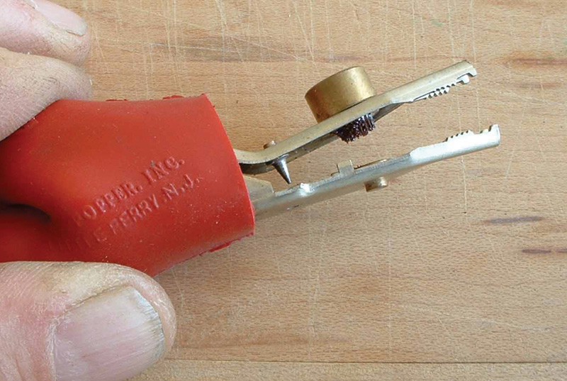
The easiest way to tap into a sensor’s signal lead is with a wire-piercing tool. This is done all the time in the real world without mishap. Just remember to seal the hole with Krazy Glue.
By the way, Mercedes-Benz (along with all other carmakers) cautions us to use only meters or testers with high impedance. That’s because there’s a possibility of current flow breaking the bond between the zirconium dioxide and the platinum, or blowing a channel through the sandwich. And if you’re checking it in parallel, an extra ground may skew the signal.
If the sensor is easily accessible, you might want to take it out for inspection. Shake it to listen for rattles that indicate a broken ceramic element, give it a careful visual exam, then hook a DMM across the pigtail and the shell and heat the tip with a propane torch (use the blue part of the flame). When it turns to a dull red, look for relatively high voltage, then move the flame away, which should make the reading drop.
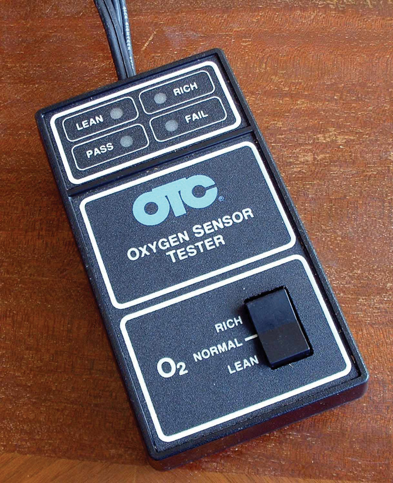
Numerous dedicated oxygen sensor testers have been offered over the years. This one’s from the mid-’80s and still works fine.
Robert Bosch gives a very straightforward procedure for testing with the sensor isolated from the PCM. Start by warming up the engine, then disconnect the sensor’s pigtail from the harness and attach it directly to your meter or tester. To check rich response, hold 2,500 rpm, and add propane to the intake until speed drops by 200 rpm. Or, pull and plug the vacuum hose to the fuel pressure regulator, which will increase psi and richen the blend. You should see the reading jump to 900 mV or more. If reaction is slow, or that voltage is never reached, try running it at 3,000 rpm for a few minutes, then check again. No improvement means you buy a new sensor.
Then, test lean response. Introduce a small vacuum leak, say by removing an accessory hose, and watch the reading. If it drops to .2V or lower in less than one second, the sensor’s okay. If it falls sluggishly, or you never see it get down to .2V, give it the 3,000 rpm treatment and try again, but it’s probably time for replacement.
Reconnect the pigtail to put the sensor back in touch with the PCM, then tap your meter into the signal wire, maintain 1,500 rpm, and you should see rapidly changing readings that average somewhere around half a volt as the computer keeps adjusting the blend. Deciding whether or not response is slow enough to justify replacement requires some judgment. A common rule of thumb for minimum activity is eight trips across the rich/lean line in ten seconds, and sometimes you can find specs for cross counts.
Sending the PCM a substitute O2 sensor signal will let you know how — and if — the system responds. While some factory manuals say you can use an ordinary dry cell to inject a rich signal, a sensor simulator would be a lot more helpful. If varying the substitute signal changes something (say, injector pulse width, loop status, ignition timing, idle speed or quality, etc.), you’ve learned two things: The wiring and connections between the sensor and the PCM are okay, and the computer itself is operational because it’s responding to this input. Ergo, the sensor becomes your prime suspect.
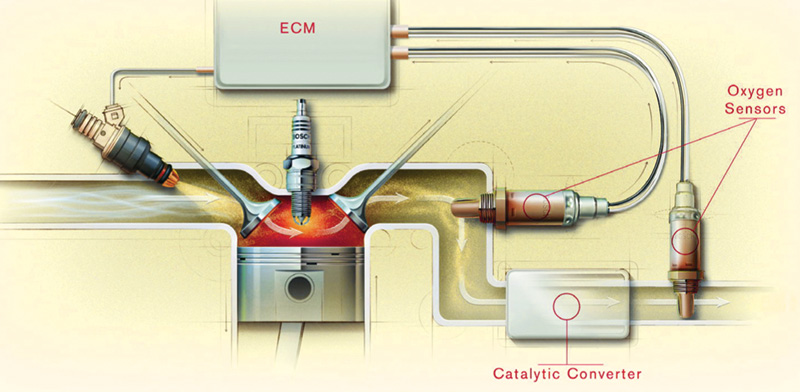
The addition of an oxygen sensor downstream of the catalytic converter makes it possible for OBD II to test the cat’s capacity and efficiency.
OBD
Will pre-OBD II (in other words, 1996 or earlier) self-diagnostics help you nail a weak O2 sensor? Not really. Sure, the program monitors this critical input, but typically it’s only looking for opens or grounds in the circuit, an always rich/always lean situation, or sensor cool down. It won’t recognize a lazy specimen. So, this sensor is a likely cause of driveability complaints even if no codes are present.
Things are different with OBD II vehicles. Not only is there a HEGO both upstream and downstream of the catalyst, but two types of tests are run on them. One monitors the sensor’s activity, and the other checks the sensor’s electrical heating element.
An oxygen sensor can fail the activity monitor for slow response rate, which is sometimes called a “big slope” for the way the wave looks on an oscilloscope. Or, it can fail for having too small a change in voltage output from rich to lean and vice versa.
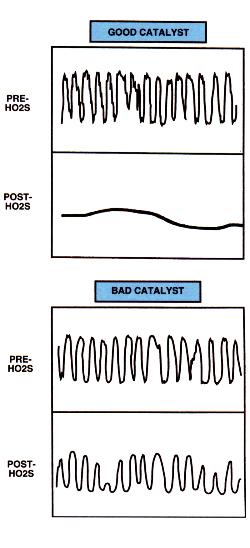
The upper wave on this scope shows the signal the upstream oxygen sensor is sending, and the lower wave that for the downstream sensor. There should be a big difference, which indicates that the catalyst has sufficient oxygen storage capability. If both waves are similar, the cat is bad.
A typical OBD II HEGO response test is done after the system achieves closed loop, and during steady state speed and load in the 30-50 mile-per-hour range. The test forces fuel control changes at high frequency. In other words, it superimposes a square wave on top of the regular injector pulse. This switches rapidly between 10% rich and 10% lean. Can the HEGO respond to this high frequency, or has it become too sluggish and lazy? And, can it produce big enough voltage swings? If it can’t satisfy both standards, it fails.
Since any oxygen sensor is only accurate when it’s hot, the HEGO heater monitor is intended to make sure the sensor is properly heated. In a common Daimler-Chrysler approach, the heating element itself isn’t tested. Instead, the change in electrical resistance that the sensor’s output circuit experiences at various temperatures is watched.
After the ignition has been turned off, the PCM sends a five-volt signal to the sensor every 1.6 seconds. As the sensor cools down, its resistance increases, changing the voltage, which the PCM reads as temperature. Once the sensor is cool enough, the PCM commands a relay to complete the circuit to the heating element, then it watches as the sensor gets hotter and hotter. If it sees the proper voltage for several pulses, it passes the sensor.
Etcetera
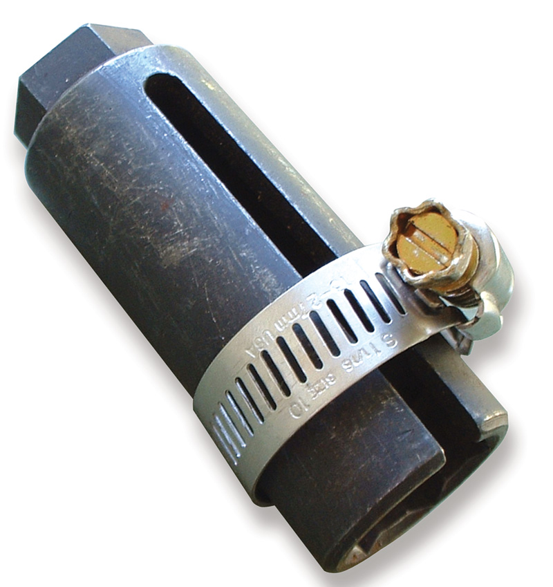
A simple trick that can save frustration: To keep your oxygen sensor socket from spreading when you encounter a case of thread seizure, just tighten a hose clamp or two around it.
We’ll conclude with some miscellaneous points:
- An oxygen sensor is an averaging device that responds to the leanest cylinder — it can’t differentiate among them. If one injector is clogged, it’ll pump enough O2 to fool the computer into thinking there’s an overall lean condition. So, the PCM will fatten up the mix, perhaps increasing emissions.
- Whenever you replace an oxygen sensor, please make sure the threads are coated with the proper anti seize compound. Otherwise, the next guy who tries to remove it may have to blast. There’s a good chance the next guy will be you.   Â
- Afraid you’ll spread your split oxygen sensor socket because the old sensor is in there so tight and you’ll have to apply extraordinary torque? Try our old trick: Slip the socket over the sensor, then tighten a worm gear clamp or two around the socket to help keep it from spreading. Of course, this is a moot point if you’re replacing the sensor — you can just snip off the wires and use a regular deep socket, perhaps even on your 1/2 in. impact gun. That ought to do it.




0 Comments