
Don’t be dazed and confused by electrical troubleshooting. This first installment of our two-part story gives you the fascinating theoretical background.
Except for the occasional spark, or the glow of a filament, electricity is invisible, and it’s hard to comprehend something you can’t see. So, it’s understandable that many technicians, novices and veterans alike, would have dark corners in their minds on the subject. When you follow a Mercedes-Benz electrical diagnostic procedure, are you just performing the steps, or do you really understand what the readings mean? The results you get during your testing will make much more sense when you can interpret the numbers, not just read them.
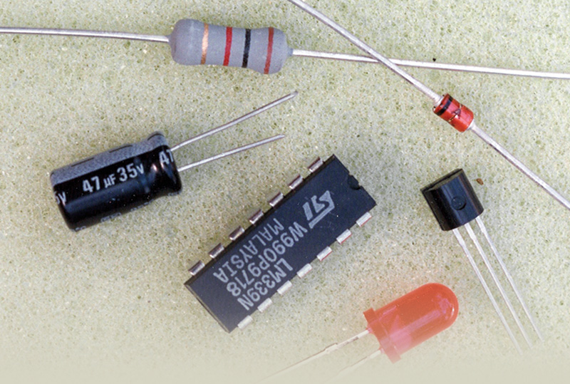
This article is not intended to make you an electrical engineer, but just to give you a start. We’ll cover only basic 12 volt, direct-current automotive circuits this time, but future articles will go into greater depth on testing and troubleshooting. By the way, we’re talking about electrical, not electronics -there’s a difference.
Pumping electrons
The easiest way to understand electricity is to think of water flowing through a pipe. To get the water to move, you must apply pressure. The amount of pressure and the diameter of the pipe determine the volume of water that moves during a given time. If you apply the same amount of pressure to a small pipe as to a large pipe, more water will move through the large pipe because it has less resistance.
Now, a little nuclear physics, greatly simplified. Everything is made up of atoms. Each atom has three major components—protons, neutrons, and electrons. The protons and neutrons are clumped tightly together to form the atom’s center or core. The electrons orbit the core, sort of like planets orbiting the sun. Protons have a positive charge, neutrons have no charge, and electrons have a negative charge. Individual atoms have no electrical charge because each atom has an equal number of the positively charged protons and the negatively charged electrons and the charges cancel each other out.
The nucleus of the atom, containing the protons and neutrons, is incredibly stable. Which is a good thing, because the term used to describe an atomic core coming apart is “nuclear explosion,†which is something that would ruin your day.
Normally, electrons stay in their orbits. But electrons are not tightly bound to the core of the atom. Under certain conditions, electrons will leave the orbits around one atom and jump into orbits around another atom, then another atom, and another atom, like a game of leap frog involving nearly countless electrons moving at almost the speed of light (186,200 miles per second). Electrons will jump from orbit to orbit because of a chemical reaction (which is what happens inside a battery), magnetic induction, or friction. The movement of the electrons is what causes an electric current — actually, it is electric current.
Two things to remember:
- It takes some external force—as we said, chemical reaction, magnetic induction, or friction—to cause electrons to flow. In other words, the other energy source is converted to electrical energy.
- No electrons are created or destroyed when there is an electric current. The electrons only move from one point to another within the circuit. As one of our editors once said, “Only recycled electrons have been used in the creation of this magazine.”
To continue our hydraulic illustration, think about a closed water system consisting of a pump, reservoir, and piping. When some external force causes the pump to move, the water flows out of the reservoir, through the pipes, and back to the reservoir. Because the system is closed, no water is added and no water is lost, it simply moves from one point to another throughout the system.
If electrons flow in only one direction, it’s called “Direct Current†or “DC.†DC is fine for relatively small electron flow over short distances, which is why it is the current found in automotive use.
For large current flow over long distances, DC doesn’t work very well. That’s why the electrical power to your home, your shop, or any other commercial application is “Alternating Current†or “AC.†In an AC circuit, current flow changes direction rapidly, going back and forth within the circuit typically at 60 cycles, or 60 Hz. Because AC is not commonly used in automotive applications (except, of course, for the charging system — the alternator produces AC, but that current flow is immediately rectified to DC by diodes for use throughout the car), we’re not going to cover it in this article.
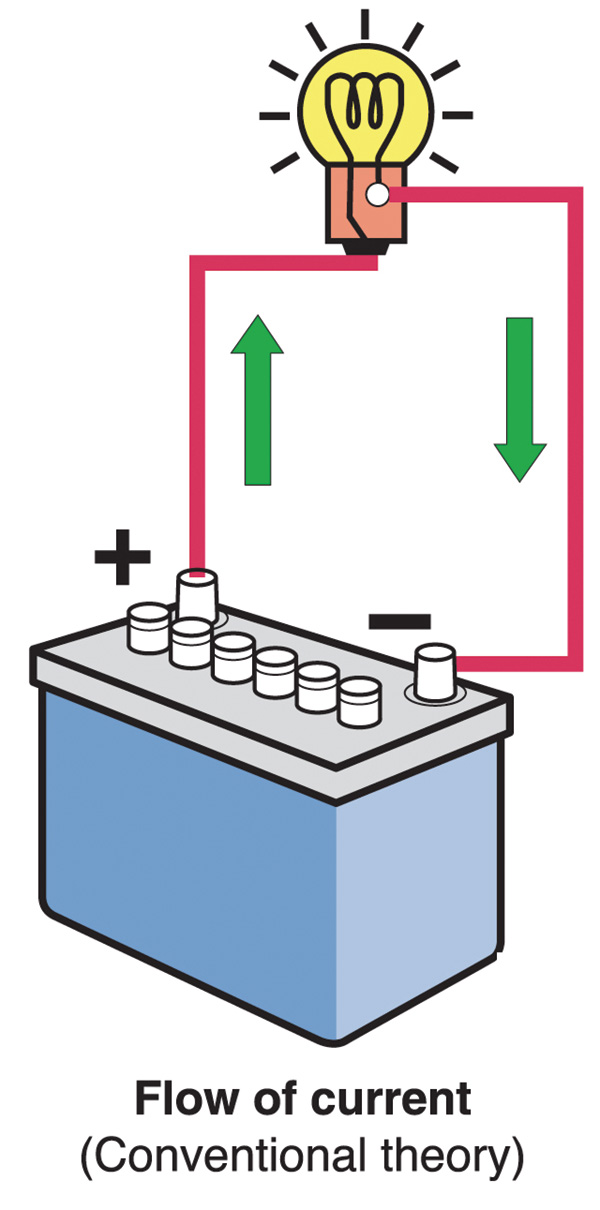
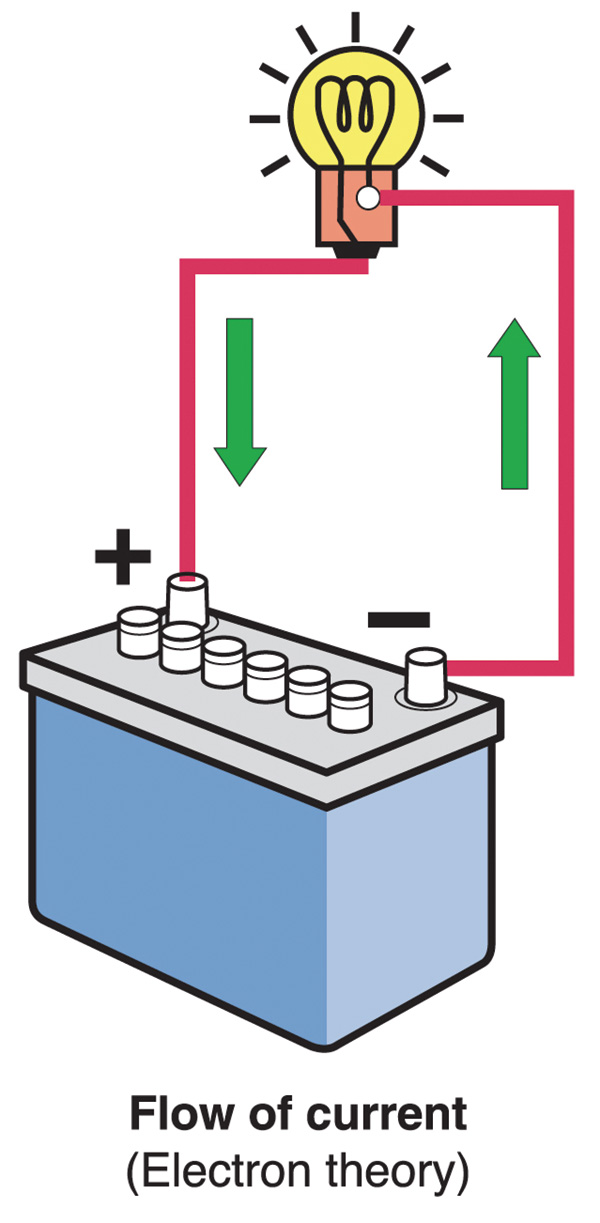
It’s interesting to note that virtually all DC wiring diagrams, including automotive schematics, are technically wrong. The diagrams show electrons leaving from the positive terminal, passing through the circuit, and returning to the negative terminal. In fact, electrons actually go the other way, from negative terminal to positive. When the earliest research into electricity was being done in the late 1700s and early 1800s, none other than our own Ben Franklin—patriot, statesman, scientist, inventor, and kite flyer—made the decision to label one terminal “positive†and the other “negative†and then declare that was the direction of current flow. Unfortunately, Ben guessed wrong, but the error was not discovered until long after the early scientific work was completed and the positive to negative idea was firmly in place.
For most DC work, however, it doesn’t really matter how electron flow is described. If you ever hear people referring to “electron theory†when talking about DC circuits, they mean electrons flowing from negative to positive, as they actually do. But most applications use what is called “conventional theory†to describe the positive to negative flow that most people are familiar with.

Players & Relationships
Electromotive force is what pushes current around a circuit. You can call it voltage potential, or the difference in the “pressure” on the electrons between the two ends of the circuit. One volt (named for the Italian scientist and Count Alessandro Volta, 1745-1827) is the force needed to push one ampere through one ohm. Or, one volt equals the difference in electrical potential between two points on a wire carrying a constant one ampere current when the power dissipated between the points is one watt.

An ampere (which appellation commemorates the French mathematician and physicist André Marie Ampere, 1775-1836), commonly referred to as an “amp,” is one coulomb per second. What’s a coulomb? It’s a charge of about six quintillion electrons (that is, a six followed by 18 zeros). To put it another way, it’s the quantity of electricity that is moving, somewhat like the number of liters or gallons a water hose can supply per second.
One ohm (from the German physicist Georg Simon Ohm, 1787-1854) is the resistance to electron flow that’s present if moving one ampere through the resistor produces a one volt drop. In other words, one ampere requires one volt to be coerced through one ohm. To continue our hydraulic illustration, it can be likened to a restriction in a water hose.

Watts (after Scottish engineer James Watt, 1736-1819 did you notice that all these guys lived at about the same time?) are similar to horsepower. In fact, one horsepower translates into 746 watts. One watt is a unit of power equal to one joule per second, a joule being a unit of energy equal to the work done when one ampere is passed through one ohm for one second. You can get watts by multiplying volts times amps. So, a five ampere bulb on twelve volts is burning 60 watts.
While the plumbing analogy we used above is hardly scientifically exact, it does seem to aid understanding. Voltage is likened to water pressure, amperage to the volume flowing, and resistance to a restriction in the hose. The amount of work this flow can do (spinning a water wheel, for example) is measured in watts, and the “pump” may be either a battery or a generator/alternator.
In a future issue of StarTuned, we’ll give you the most important practical points of this topic, which amount to applied science at its most interesting.
|


0 Comments