
The air mass meter, or MAF (Mass Air Flow) sensor “weighs in†as an important component for engine performance
For a small box with no moving parts that just sits there with air blowing through it, the air mass meter or sensor (also known in SAE standardized terminology as a mass air flow sensor, or simply MAF), has an important job. The MAF measures precisely how much air has been drawn past the air filter and is on its way to the intake manifold. The signal the MAF continually sends to the Engine Control Module (ECM) is a critical input for controlling the amount of gasoline injected into the engine.
The performance of the MAF is mind-boggling when you study its operation. We almost never think about the air that surrounds us. Air is just there. About the only time we notice air is when it is moving fast enough to feel its motion. Even then, we focus on the motion, rather than on the air itself. We’ve all stood outside, felt the movement of air increase, and said, “The wind is picking up, I wonder if a front moving in.†But has anyone ever said, “The wind is picking up, I wonder how much the amount of air moving past my face has increased compared to a minute ago?â€
Whenever we do think about air, it is almost always in terms of volume (cubic feet) or pressure (psi). For a MAF, volume and pressure aren’t important, only the weight of the air entering the engine is. That’s why it is called a Mass Air Flow sensor, using the scientific definition for Mass: the property of a physical object that measures the amount of matter it contains. Mass is also what causes an object to have weight in the presence of gravity.
Why is measuring the weight, not volume, of air going into the engine so important? Because combining air and fuel based on weight is the key to optimal power, fuel economy, and low emissions. It is surprising how many technicians don’t realize that the ideal air/fuel ratio (stoichiometric ratio) of 14.7 to 1 is based on weight, not volume (which would be something like 2,000 to 1). Theoretically, if you combined 14.7 pounds of air with 1 pound of gasoline, blended the mixture under optimal conditions, then set off a spark, the mixture would burn completely, yielding the maximum amount of power with no emissions except CO2 and H20.
No engine can achieve this perfect combustion in real-world conditions. But a Mercedes-Benz with OBD II comes about as close as you can get while driving down the highway. Although OBD II uses inputs from all the engine management sensors to keep the air/fuel mixture as close as possible to the ideal 14.7 to 1 stoichiometric ratio, MAF input is critical to overall engine management.
Vacuum Inadequate
Linking the amount of air entering the engine to the amount of fuel delivered to the cylinders is as old as the internal combustion engine itself. With the MAF and other components of OBD II, the effort to meter precisely the amount of fuel to the amount of air in the cylinder has been taken to an all-time high in sophistication and accuracy.
Carburetors and early Bosch electronic fuel injection systems relied on vacuum created by the pistons’ intake strokes to regulate fuel deliver. On a carb, air moving through the venturi created a vacuum that allowed atmospheric pressure to force gasoline from the fuel bowl. The more the throttle was opened, the more air moved through the venturi, the stronger vacuum and the more gasoline entered the intake stream.
The Bosch D-Jetronic injection system, introduced nearly four decades ago in 1968, used a vacuum sensor (the “D” stands for Druck, which is pressure in German) to regulate fuel delivery. As airflow changed, the vacuum sensor sent the signal to the circuit board that was used to calculate injector pulse width, hence the amount of fuel delived.
In 1974, Bosch replaced the vacuum sensor with the air flow meter, or VAF (Vane Air Flow) on its L-Jetronic injection system. The L stands for Luftmengenmessung, which is German for air quantity measurement. The system was also called AFC (Air Flow Controlled) fuel injection.
The VAF was a big improvement over the vacuum sensor. A vane inside the meter pivoted against spring pressure. The more air entering the engine, the more the vane rotated open, as air movement decreased, the vane returned toward its closed position. As the vane moved, it turned the shaft of a variable resistor, causing the signal to the computer to change. L-Jet was simple and more accurate than any of the early vacuum systems for regulating fuel delivery.

The vane air flow meter of L-Jetronic was really a simple variable resistor. Variations in the volume of air entering the intake as controlled by the throttle changed the voltage signal to the computer.
However, no vacuum or other system based on air movement was fast enough and accurate enough to meet the ever-tightening emission control standards introduced through the late 1980s and into the 1990s. The problem comes back to the fact that all vacuum and related systems measure air volume, not air weight. Volume is okay, if nothing changes. At a given temperature, pressure, and moisture content, the weight of a cubic foot of air is constant. Any change in temperature, pressure, and moisture content and the weight of the air in a cubic foot changes.
The VAF and the vacuum systems operated best under “normal conditions†which meant driving near sea level at moderate temperatures and moisture levels. Drive a Mercedes-Benz with VAF to “mile high†Denver and the engine would run rich because at the higher altitude — there was less air, by weight, in a cubic foot than at sea level. Drive during a cool night through Death Valley, which is nearly 300 feet below sea level, and the engine would run lean because cold air at lower elevations is denser. A cubic foot of air in Death Valley weighs more than a cubic foot of air in Denver.
How It WorksÂ
To meet strict emissions standards, optimize performance, and maximize fuel economy, what was needed was a system that instantly and accurately measured the weight of the air entering the engine instead of monitoring the volume. The sensor or meter would have to compensate for changes in air temperature, pressure, and moisture content, in addition to reacting to shifts in throttle position. Enter the MAF.
Bosch introduced the first version of the MAF, its “hot wire†system, in 1984 as part of the Motronic engine management system. The design was later replaced by the current version, the “hot film†MAF.
The operation of the MAF is simple, but it required sensitive electronics to make it practical. As soon as the engine is started, a small electric current is supplied to the wire or film inside the MAF. The film is kept at a constant temperature, typically about 180° F. (82° C). Air moving past the wire or film cools it. To counter the cooling effect, the current flow to the MAF fluctuates depending on the amount of air going past.
Unlike earlier air movement monitors that measured volume, the airflow’s cooling effect on the wire or film varies directly with air temperature, density, and humidity. The amount of current needed to maintain a constant temperature across the MAF film is a measure of the air’s mass or weight. The current level changes the signal that the MAF sends to the computer, which, in turn, is used to regulate injector pulse width.
At idle, the low airflow level requires little additional current to maintain MAF temperature and the signal to the computer is typically about 0.6 V. At wide open throttle, the rush of air requires a much greater current to maintain film temperature and the signal to the computer can be more than 4 V.
Problems

Whether hot wire or hot film, various styles of air mass meters have been used in Mercedes-Benz vehicles over the years. Regardless, the cooling effect measured across a Wheatstone bridge is the same.
Problems with a MAF typically generate consumer complaints of no power, stumble or hesitation, rough idle, both cold and hot hard starting, and possibly stalling. Of course, the symptoms a bad MAF produces can also be caused by other defective components. So, always check the basics first—ignition, compression, fuel pressure and volume, etc.
There is one “big hammer†approach to MAF testing you can use, especially when engine performance is really raggedy. With the key off, unplug the MAF harness. Start the engine, if performance is noticeably better in the resultant “limp -in” or “fail-safe” mode, it’s time for a new MAF.
Always do a through visual inspection or, even better, a leak test, for an air leak downstream from the MAF. Unmetered air, commonly called “false air,” entering the engine behind the MAF isn’t accounted for by the computer as it sets injector timing. The resulting lean condition causes all kinds of drivability complaints. Leaks from deteriorating air ducts, PCV hoses, etc. can be hard to find, so do an eyes and hands inspection—look closely at the ducts and hoses and squeeze them to detect cracks, holes or mushiness.
OBD II continually examines the MAF, looking for out-of-range signals. OBD II also compares the actual MAF output signals received by the computer to expected values based on rpm, manifold absolute pressure, throttle position, and intake air temperature. If there is a discrepancy between actual and expected MAF readings, a trouble code will be set.
A word of caution: Blind faith in codes can get you into trouble. Consider trouble codes as guideposts, not as the absolute word on what’s wrong. Do basic testing and rely on your experience before you accept a code as the final word on what is wrong.
With no moving parts, a MAF won’t break or wear out, but things can still go wrong. One problem isn’t the MAF’s fault, but it is the victim.
MAF contamination insulates the hot wire or film, so air movement doesn’t have the same cooling effect. The MAF signal will be sluggish and the value won’t accurately reflect the true mass of the air going by. Contamination typically is caused by a faulty air filter that releases fibers, an air filter long overdue for replacement, aftermarket filters that use any type of oil coating, and prolonged driving in extremely dusty conditions. Older, hot wire, MAFs are more susceptible to contamination than hot film units, but given enough dirt or grunge, any MAF can become contaminated.
If the MAF is contaminated, you have to do two things: Replace the MAF with a new Mercedes-Benz unit and solve the source of the contamination—replace the defective air filter, recommend more frequent maintenance service, remove an aftermarket filter that uses oil and replace with a Mercedes-Benz OE filter, etc.
A MAF can’t work if it isn’t getting power. There are two power feeds to a MAF. One is the OBD II input voltage, and the other is the current feed to heat the wire or film. If either feed is missing, the MAF won’t work, but the problem is somewhere in the wiring, not in the MAF itself. You can check MAF output voltage with a digital voltmeter or a lab scope. You should see a smooth, linear change in output voltage to the ECM as engine speed changes. Some technicians blow shop air into the MAF when testing to see if the voltage increases. In addition to a smooth change in voltage, compare output readings at different engine speeds to the Mercedes-Benz specs for the model and engine you are working on.

Here’s the single most common cause of MAF related symptoms and trouble codes. Nobody has yet satisfactorily explained exactly why these ducts fail this way, and it happens on all makes and models.
If output voltage shifts are jerky, not smooth, or if the readings don’t match specifications, it’s time to replace the unit with a new MAF from Mercedes-Benz. Make sure the output voltages match the Mercedes-Benz specs. On some systems, close isn’t good enough. A variance of as little as 250 millivolts from spec can be enough to cause problems.
Trimming
When testing a MAF, also check the multiplicative and adaptive fuel trim numbers. These numbers represent the amount of correction the computer is applying to the base injector pulse width, based on the input received from the MAF.
Multiplicative numbers are roughly equivalent to what SAE calls Long Term Fuel Trim (LFT). Multiplicative values are listed in percentage numbers, either plus or minus. Additive fuel trim is the equivalent of SAE’s Short Term Fuel Trim (SFT). Additive fuel trim is shown in tenths of a millisecond, either plus or minus, and relates directly to the actual injector pulse width as it would be measured with a lab scope.
Positive numbers on both additive and multiplicative at idle usually indicates an air leak.
Multiplicative numbers that are positive (greater than 10%) with adaptive numbers that are negative at idle are often a good tip-off that the air mass meter has drifted out of calibration. If you have a high-end scan tool, clear the adaptive values, then test drive the vehicle. Without the multiplicative fuel, the engine will run poorly if the MAF is bad. Performance will be sluggish and often the engine won’t be able to reach 4,000 rpm until the computer has time to readapt by restoring the additional pulse width.
Adaptive numbers that are negative indicate a rich condition. This occurs much less often than the opposite problem. When you see negative numbers, look for anything that overloads the engine with fuel including a faulty fuel pressure regulator, blocked or restricted line on a return-type system, or defective injectors that are leaking fuel.
Never be too quick to condemn a MAF, even when any codes say the MAF is the problem. The little box that doesn’t do anything but weigh the air as it flows by is pretty dependable and the actual problem could very well be somewhere else under the hood. So always do comprehensive testing and troubleshooting before replacing the MAF.
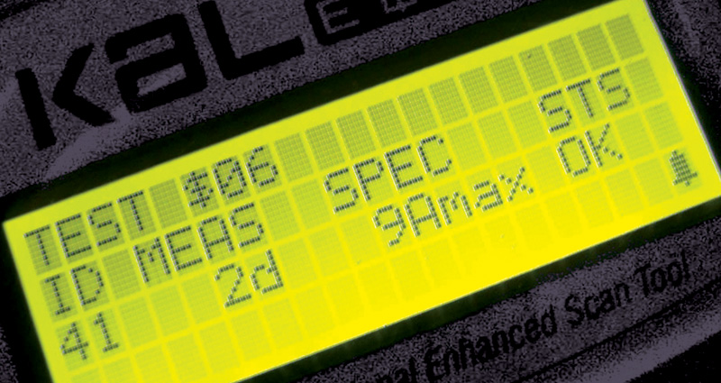
Mode$06
The Society of Automotive Engineers (SAE) document J1979, which outlines the operation of the OBD II system, requires nine modes of operation:
Mode $06 can be useful, if your scan tool can access it and translate the readings. However, most European carmakers, including Mercedes-Benz, don’t have much faith in its diagnostic value. Mercedes-Benz has some potentially useful Mode $06 codes that reference OBD II intake leaks. However, a Mercedes engineer tells StarTuned, “Instead of using Mode $06 for detailed information on the leak, most technicians just hook up a smoke machine to find the leak. “At Mercedes, Mode $06 is used primarily for engineering development, not for service work.†So, as a Mercedes-Benz service specialist, learning Mode $06 is like taking a class in calculus. Yes, you will be more knowledgeable, but the odds are slim that you will ever use the knowledge servicing a Mercedes-Benz vehicle. |
Â


0 Comments