This technology is essential to bringing Mercedes-Benz vehicles into the future.
In the 1980s, Mercedes-Benz faced a “wire crisis,†as indeed did all carmakers. This was because of the demand for more and more onboard electronic devices. Mercedes-Benz was continually adding more sensors, actuators, controllers, and other electronic components to retain its leadership position in automotive technology, to comply with various government regulations for fuel economy, emission control, and safety, and to meet consumer expectations for increasingly sophisticated comfort and convenience features.
Developing the electronic devices was one issue, but a more serious problem was connecting the components so they would work together properly. Old school technology required separate wires to connect every device. Sometimes, multiple wires had to run between two devices. For example, if two sensors reported to a controller, and the controller operated two devices based on sensor inputs, the controller would be the center of a spider web of four to eight wires. The exact number of wires joining the devices would depend upon the circuitry to provide reference voltage and signal voltage between the sensors and the controller and the connections needed for output and feedback between the controller and the actuators. Whenever a new device was added, entire wiring looms would have to be redesigned to accommodate the latest change.
Continuously adding more wires to a vehicle causes many problems:
- Manufacturing costs increase because additional wire means more material and labor are needed to assemble the vehicle. The fact that wire must be uniquely color coded further increases manufacturing cost.
- Finding places to route the wiring gets more difficult as the amount of wiring increases. According to some industry estimates, a mid-size car can have up to three miles of wire!
- More wires means more weight, which hurts performance and fuel economy.
- Fat wiring looms make diagnosis and repair more complex.
- Connecting a bundle of wires, especially at the controllers, becomes more difficult as the number of wires increases.
Just Two Wires
The wire crisis was solved by CAN bus technology, which was quickly adopted by Mercedes-Benz and is now used in all its vehicles. CAN stands for “Controller Area Network.†“Bus†is an electrical/electronics term for a device or system that links multiple components together.
CAN bus was developed in the late 1980s as a cooperative venture between Intel and Robert Bosch. The two firms realized that the wire crisis was not limited to the automotive industry. Any manufacturer of digital devices faced the same problem—trying to fit more wires in less space as components became increasingly complex and sophisticated. CAN bus technology was so successful at reducing wiring use, it is estimated that literally hundreds of millions of devices are manufactured each year using one or more CAN bus networks. Â
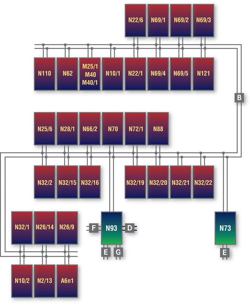
Mercedes-Benz first used a CAN bus in MY 1992 on the 140 model. Today, every Mercedes-Benz has multiple CAN networks. The current C-Class has three CAN networks, one for the engine electronics, one for diagnostics, and one for the body (there is a fourth CAN, but it supports diagnostics and isn’t a factor in service work). The most extensive use of CAN bus is on the current S-Class, which can have up to eight separate CAN networks including the Interior CAN, Drive Train CAN, Diagnostic CAN, Chassis CAN, Front end CAN, Vehicle Dynamics CAN, Telematics CAN, and the Central CAN! Just about any electron that moves on any circuit in the S-Class passes through one or more CAN networks.
According to one Mercedes-Benz service engineer, today’s Mercedes-Benz vehicles, with all of their features and innovations, could not be built without CAN bus technology. It would be impossible to effectively link together all the electronic components and systems that make a Mercedes-Benz vehicle a Mercedes-Benz.
 CAN bus replaces the thick bundle of multi-colored wiring with just two wires. One is the “CAN-high†wire, the other is “CAN-low.†The two wires are twisted or braided along their length to limit the amount of electrical “noise” that can enter into the wiring, and both wires are connected to every device on the network.
Two wires are used because, in a CAN bus, signals may be redundantly “pulled up†on one wire or “pulled down†on the other. In electronics engineering, this is known as dominant recessive logic for signal transmission. Because of this setup, CAN bus networks are virtually immune from electrical interference caused by external devices that are not part of the network. Interference can still disrupt a CAN network, but such problems are rare.
In electronic terms, “node†is a generic term for any device on a given CAN bus network. All nodes in an automotive CAN network are capable of both sending and receiving messages. The type of message determines if a node will transmit it or receive it. Although nodes can both send and receive, sensors and other devices that provide input data to a control module mostly transmit. Actuators that respond to signals from a controller are mostly receivers.
Benefits
Mercedes-Benz has quickly adopted CAN bus technology because of its many advantages. CAN bus:
- Replaces thick wiring harnesses with just two wires, saving weight, space, and installation costs.
- Not only reduces the wiring used, but can also reduce the total number of components required. Messages from any component can be sent to any other device on the network. With links between CAN bus networks, a message can be sent from any component to any other location on the vehicle.
- Is energy efficient. A CAN bus network operates on low voltage — the exact voltage varies from vehicle to vehicle and by the CAN bus type. When no signals are being sent, the network goes into a “sleep†mode, immediately becoming active when a signal is sent.
- Is more reliable because with less wiring and fewer components there aren’t as many things that can go wrong. The double twisted wire setup is extremely fault tolerant. Transmission failures or errors are very rare in a CAN bus network.
- Is easy to troubleshoot. The system is programmed to identify any node or component that is not operating properly and will set a trouble code.
- Makes adding new devices easy. All that needs to be done is connect the device to the network and reprogram the controller.
| Advances of CAN-bus Technology | |
|
Lower cost of wiring |
Lines from sensors must only be lead to the nearest control unit where the measured values are processed to form a data telegram and are placed on the CAN data bus. Actuators can also receive control signals from a different control unit which receives the data telegram through the CAN bus and then uses this information to calculate a control parameter for the actuator. |
|
Improved electromagnetic compatibility (EMC) |
 |
|
Fewer plug connections |
 |
|
Fewer pins on the control units |
 |
|
Weight saving |
 |
|
Fewer sensors |
Signals from one sensor (e.g. ECT sensor) can be used several times |
|
Better diagnosis |
Because signals from one sensor can be received by several receivers, it can be assumed if a fault is displayed by all systems which use a particular signal, that the sensor is defective or that the control unit which processes the signal is faulty. If only one system displays a fault, even though the signal is used several times, the fault is usually at the processing control unit or at the actuator. |
|
Fast transmission rates |
Mercedes-Benz uses transfer rates from 83k bits per second (bps) to 500k bps. Faster speeds could be used because CAN-bus will operate at up to 1M bps. |
|
Several messages can be transferred in succession on the same line |
 |
Not Multiplexing
Don’t confuse a CAN bus with “multiplexing.†Although a multiplex network shares the benefits of connecting multiple devices to a single network, the technologies operate differently.
In a multiplex network, a single wire connects all the devices. Each device has a unique “address†on the network. A signal from one device is sent directly to another unit on the network based on the receiving network’s unique address. The message skips over or bypasses all other components.
On a CAN bus, all nodes or components send and receive data equally. In theory, a node on a CAN bus could send a signal to all of the other nodes at the same time. But each message that is sent contains an identifier code. The message goes to all components on the network. Each receiving component, “opens†the message and immediately looks for the identifier code. If the code isn’t the correct one for the specific node or component, the device “discards†the message.
The distinction between unique addresses in a multiplex system versus unique identifier codes in a CAN bus network might seem to be splitting hairs. But using identifier codes is a key reason why it is easy to add components or modify a CAN bus network. Sending messages to all nodes, but only allowing a node to “open†messages that pertain to its function makes it much easier to program a CAN bus network than a multiplex system with unique addresses.
Included with the CAN identifier code is a message priority status, known as the arbitration process. Greatly simplified, arbitration occurs when two messages are being sent to the same node at the same time. As the transmitter node sends a message, it compares the bit sent/transmitted with the bit received back from the network. If the transmitter detects that the received bit and transmitted bit are different, then it ceases to transmit, since it knows a message with higher priority is being sent at the same time. The message with a higher priority will be transmitted without interruption. It will try again after an idle time is reached.
In addition to priorities for each node, messages can be ranked by the frequency by which the CAN bus receives them. For example, a signal to initiate the anti-lock brake system would be sent with increased frequency (or at quicker intervals) than a message to the climate control system to adjust the interior temperature.
At maximum speed, a CAN bus network can send signals at speeds of up to 1M (mega) bits per second (bps). A bit is a digital signal for 0 or 1, the basis for all digital communications. Mercedes-Benz does not operate its CAN bus networks at the maximum potential speed. Speed is limited to a balance between what is required for speed and how much noise (interference) the network can tolerate. The faster the network, the more susceptible it is to electronic noise that will interfere with its operation. The fastest any current Mercedes-Benz CAN bus network operates at is 500K (500,000) bps. Some networks operate as slowly as 83K bps.
The 500K bps CAN bus networks are used for drivetrain and other critical systems that require higher throughput. The slower networks are used for various interior systems, which are not as time critical.
The higher and lower priority messages and transmission intervals are in “electronic time†which is measured in milliseconds over a relatively short distance. A human observing the operation of a CAN bus without the use of special test equipment would not be able to sense any difference in priority or speed. To humans, a CAN bus does everything all at one time, and all CAN bus networks are very, very, fast. For example, a single bit transmit time in a 500 Kbps is 2 micro seconds and 83.3 Kbps is 12 micro seconds.
Mercedes-Benz also uses a LIN network that is a slow (19.2K bps) system used for controlling some interior functions. Another network is MOST, a very high-speed network used for the fiber optics that control audio and navigation systems. MOST replaces the older D2B networking technology.
Reliable
CAN bus networks are reliable and getting better. On the latest Mercedes-Benz vehicles, CAN network problems are rare. In fact, when troubleshooting, a problem with the network should be the last thing, not the first thing, that you focus on.
Most of the time, the problem will be with one or more nodes or components on the network. Typically, a component is either not sending out signals or it fails to respond properly to messages that are addressed to it.
If your troubleshooting has eliminated the components on a network, don’t begin to check the network itself until you verify that there is normal battery voltage available and the charging system is operating properly. Correct any battery/charging problem before proceeding to test the CAN bus.
Getting the correct voltage reading for a CAN bus only means that necessary voltage is present, not that the network is operating properly.
A visual inspection can spot most of the common physical problems with a CAN bus including:
- Corrosion, which can be caused by water leaks or other moisture sources coming into contact with the wiring.
- Physical breaks in the wiring.
- Shorts to battery voltage or ground, which are usually found using your DMM.
- Damaged connectors.
- Circuits that have been tampered with. If another technician has tried to “fix†a CAN bus by rewiring it, or has added a component that was not originally part of the system, the network won’t work properly. Splices, replaced wires, wires that do not have the correct turns per inch in the braiding, etc., will change the length of the wiring, which will interfere with network operation.
With a good quality DMM and lab scope, plus the specific service information for the vehicle you are working on, you can test a network for signal patterns, voltage drop across the components, and system resistance. Make sure all resistance readings are within specifications. A CAN bus may operate with the wrong resistance, but signal problems are more likely when the resistance isn’t within limits. This is more critical on the 500 Kbps networks where there are terminating resistors that maintain this balance.
Interference, although rare, can still happen. Interference can confuse you because the problems may mimic a short or communication failure among nodes. A defective alternator is a common cause of interference, which is one reason why you must verify good charging system operation before troubleshooting a CAN bus. Look for a clean signal free of any glitches in the pattern that may indicate transient interference entering the network or control modules that may be sending out errors. If needed, compare the signal of the suspect vehicle with that of a known good vehicle.
The other major cause of system interference is an aftermarket component that has been improperly installed. You’ll have to disconnect each device, one at a time, and check to see if the inference problem is eliminated.


0 Comments