Ignition, fuel distribution & fuel supply make up the three points of driveability diagnosis
Mercedes Benz manufacturers some of the most technologically advanced vehicles in the world. Many of the company’s advancements help reduce wiring, increase self-diagnostic capability, and, above all, provide an additional level of safety. This kind of progress, however, comes at the price of increased complexity when it comes to driveability diagnostics.
Always keep in mind that there are three major things to think about whenever you’re confronted with a driveability problem: ignition, fuel injection control, and fuel supply. You could call them the three points of the Mercedes-Benz star because each is critical to good performance. If any one fails, the engine will not run, period. In this installment, we’ll focus on fuel supply, its electronic controls in particular. Fuel supply logic
Of the three points, the fuel supply system is often considered the simplest to control. The goal is to have it provide proper fuel pressure and volume for engine cranking and running, and only during engine cranking and running. It would be a waste and very dangerous to have the system generate pressure for any appreciable period of time without the engine running.
Mercedes-Benz has advanced the logic of fuel supply control for several good reasons — ease of manufacture, component consolidation, and increased safety. Due to the integration of computer controlled systems, fuel supply can be disabled after an accident in which the SRS has been activated. This also means that there are additional factors involved in getting the fuel pump to run. Very often these factors are not directly linked to the fuel supply system. Here we’ll go over the direct and indirect control of fuel supply.
Previous to 1994, Mercedes-Benz utilized a fuel pump relay that assured that no fuel would be pumped if the engine stopped running. It would close for one second during cranking, but if it received no rpm input, it opened again, interrupting the circuit to the pump(s).
When it isn’t incorporated into a control unit, this evolved into a four-prong fuel pump relay. This has terminal designations that are universal in operation and wiring according to DIN (Deutches Industrie Norm, which sets German standards). The relay has two circuits in it. They are the switched circuit and the control circuit. The switched circuit is made up of terminal #30, which is the power supply to the relay, and terminal #87 which is the output of the relay. This output is actually the voltage to the pump. The switched contacts are normally open, and are only closed when the control portion of the relay is “energized.†The control portion is made up of terminals #86 and #85. Depending on how Mercedes-Benz chose to energize the relay, terminal #86 is either powered up with the ignition key, or by the fuel injection control unit (ME). This terminal is attached to the coil inside the relay, and the coil is also attached to terminal #85. This terminal is either connected to whatever control unit is in charge of turning on the fuel pump relay, or directly to ground. In essence, the relay is energized either by providing power or ground to the control coil.
Fuel pump relay
Since ’94 when Mercedes-Benz designated its vehicles C-, E-, and S-Class, it has used a fuel pump relay. M-B wiring diagrams give every component on the vehicle a letter and number designation. The fuel pump relay is K27. The component designation may stay the same from model to model, but its location will vary. On the 202 chassis (’94 to ’01 C-Class), the relay is mounted next to the rear fuse box in the trunk on the passenger’s side. Before November of ’94, there was an additional 25 amp fuse mounted in the rear fuse panel (Component ID F4), which provides power to the switched portion of the relay, terminal #30. After December of ’94, direct battery power is fed to the fuel pump relay switched circuit, so the only protection is the 30 amp fuse in the relay. This relay is controlled by the HFM control unit. In this case, relay terminal #85 is grounded all the time at the same point where the fuel pumps are grounded. The HFM control unit provides power to the control coil of the relay terminal #86 to energize it. It commands the relay on for one second, and also after it receives a signal from the crankshaft sensor.
In ’97, both relay control and location were modified. At this point, the fuel pump relay is either incorporated into the relay module (mounted in the electronics box in the engine compartment on the passenger’s side by the firewall, or in its’ original location in the trunk). So, here we can have one of two options for controlling the fuel pump circuit. If the fuel pump control is from the relay module underneath the hood, then the fuse for the switched circuit is also incorporated in that same relay module. If the location of the relay is still in the trunk, the fuse for that switched circuit is in the rear relay box. The fuse in the relay was eliminated. In this case the relay control circuit has an ignition switched power supply, and the HFM provides the ground to energize the relay.
Crash signal from SRS ÂÂÂÂ
Starting with the ’99 model year, Mercedes-Benz introduced the Crash Signal, which comes from the SRS control unit. A single wire connects this to the ME control unit. This allows SRS to signal the ME in the event of a crash that involves an air bag deployment. The ME control unit will then shut off the fuel pump relay to prevent the possibility of a ruptured fuel line releasing fuel at an accident scene. This additional control must be considered during a diagnosis of a “no start, no fuel pressure†situation. These vehicles very often come from body shops where they’ve been repaired after an accident. There should be a code in the HFM indicating that the fuel supply system has been shut down due to a signal from the SRS.
To further advance computer controls starting with the 203 chassis, (C-Class ’01 and later), then the 211 chassis (E-Class ’03 and later) Mercedes-Benz has incorporated the fuel pump relay into the rear SAM (Signal pickup and Activation Module). As a result, the engineers had to designate the relay module/fuel pump relay N10/2kA. The “N†indicates a control unit, the “k†indicates that it’s a relay, and the “A” indicates its location in the control unit.
Despite the fact that the “relay module†is called a “module,†there is direct wiring between the fuel pump relay switched circuits and the control circuits. Here, care must be taken when diagnosing “no fuel pressure†issues. There are two fuses in this fuel pump circuit. One fuse is for the switched portion of the relay and the other fuse is for the control circuit. The fuse for the switched circuit is mounted in the rear SAM. This is the actual power that is being supplied to the fuel pump and/or fuel pump control module.
Why the blown fuse?
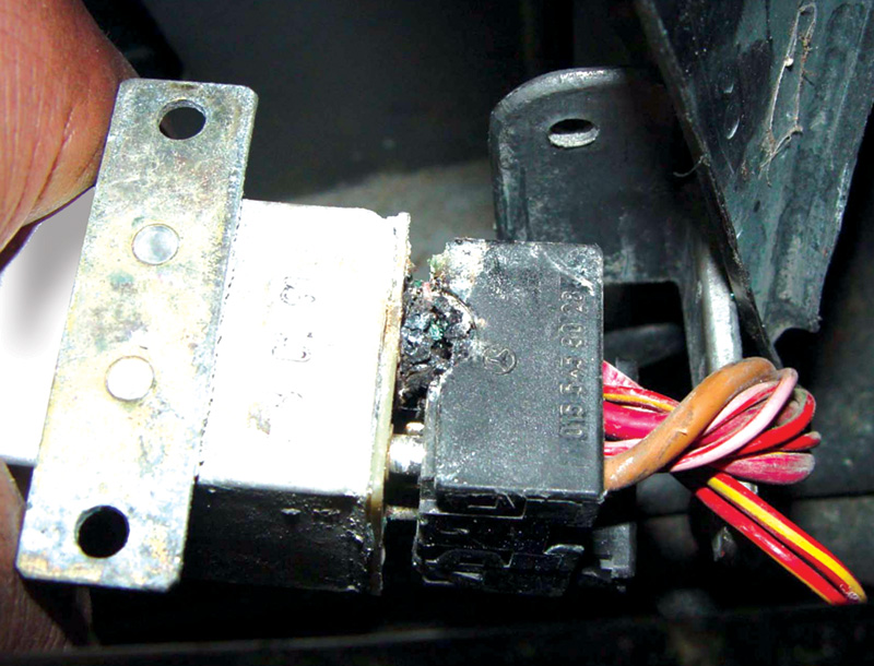
There are three possible causes for a blown fuse here: the wire after the fuse is shorted to ground, the fuel pump control module is shorted to ground internally, or the fuel pump has increased its current draw to the point that it exceeds the fuse’s amperage limit. If the fuse in the rear SAM is okay, then check the fuse for the control circuit, which is mounted in the front SAM. If this fuse is blown, the fuel pump relay will not be activated, and as a result the fuel pump relay in the rear SAM will never receive voltage. Either fuse being blown could lead to a “no fuel pressure†situation. The fuse in the front SAM receives its power from the engine relay, which is also incorporated into the front SAM.
With E-Class vehicles (124, 210 & 211 chassis) in ’94, the fuel pump relay is mounted in the engine compartment behind the battery along with the Over Voltage protection relay and the fuel injection control unit. Constant battery voltage is supplied to the switched circuit with the 40 amp fuse being incorporated in the relay. On the control circuit side, the relay is constantly grounded at terminal #85. The HFM provides the power to energize the relay on pin #86. Once again the relay is activated for one second when the ignition key is turned on, and also continuously after receiving a crankshaft signal. In ’95 and ’96, the relay is relocated under the rear seat on the passenger side, but everything else pretty much stays the same.
Revamped
With the ’96 model year, Mercedes revamped fuel supply control. Both the fuses and the relays are all incorporated into the relay module. This is mounted in the electronics box in the engine compartment on the passenger side by the firewall. This module also houses the HFM power supply and electric air pump relay as well as all the fuses for those systems. Production dates are important in diagnosing “no start, no fuel pressure†symptoms. If the vehicle was manufactured before June of ’96, the switched circuit receives its voltage supply through fuse f5. This voltage passes through the switched circuit and on to the fuel pump. The control circuit is constantly grounded, and the ME control unit provides power to the control circuit to energize the relay.
Vehicles manufactured after June of ’96 are slightly different. The control circuit of the relay is supplied voltage from fuse f3, which gets its power from the ME power supply relay. The ME control unit grounds the fuel pump relay for one second after the ignition key is turned on and also after receiving a crankshaft signal. So, a blown f3 fuse will get you “no fuel pressure,†but you will probably not have injector pulse, either (or spark, for that matter). The switched circuit of the fuel pump relay receives its power supply directly from the battery through fuse f5. This is the voltage that is actually supplied to the fuel pump. A blown fuse here may indicate that the fuel pump wiring is shorted to ground, and/or the fuel pump is drawing too much current and may have to be replaced. After March of ’97, the fuel pump relay is once again mounted underneath the rear seat on the passenger side. Vehicles built before June of ’96 have the switched circuit of the relay constantly powered up by a 25 amp fuse (#6) in the rear fuse box. The control circuit receives ignition-on voltage at pin #86 of the relay, and pin #85 is commanded to ground by the ME to energize the relay. In vehicles built after June of ’96, everything is the same except that instead of the control circuit receiving voltage from ignition-on, it receives it from the 20 amp fuse f5 in the relay module mounted in the electronics box.
In ’03, the E-Class received the same treatment the C-Class did, relocating the fuel pump relay in the rear SAM. The same operation for fuel pump control is still used. Through the 25 amp fuse (#53), the front SAM provides power to the fuel pump relay’s control circuit terminal #86. The HFM directly grounds the control circuit terminal #85 of the relay to energize it. The 15 amp fuse (#4) in the rear SAM provides voltage to the switched circuit terminal #30 of the fuel pump relay. After the relay is energized, the relay provides power out of terminal #87 to the pump.

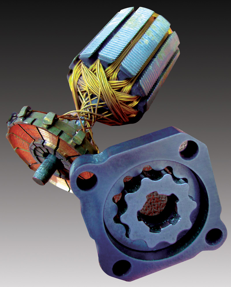
As a fuel pump’s commutator and brushes wear, it tends to draw more amperage than the system is designed to handle.
Finally, on the S-Class models there are some subtle variations. From ’94 through ’99 models (140 chassis), the fuel pump relay is mounted in the rear fuse panel. The relay’s switched circuit receives its power from the 30 amp fuse #13 in the rear fuse panel. The control circuit of the relay, pin #86, receives its voltage from a base module, which is a power distribution unit that provides current to multiple computer-controlled systems on the vehicle. This voltage supply from the base module also provides power to the ME control unit. When the ME wants to energize the fuel pump relay, it provides a ground to terminal #85. This is done with the ignition key turned on for one second and after the HFM receives a crankshaft signal.
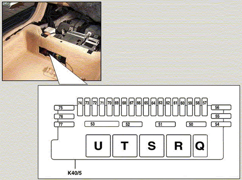
There were some significant changes in the 2000 model year when the S-Class evolved into the 220 chassis (215 for the two-door coupes), especially with the advent of the V12 and turbo models. A rear relay module, designation K40/5, controls the fuel supply system. This module is mounted below the seat on the passenger side, but you do not need to remove the rear seat. There is an access panel you can pull out to expose the relays and fuses. The control circuit of the fuel pump relay, pin #86, is powered up by the right front fuse and relay module. The ME control unit provides the ground to energize the relay. Fuse f52, which gets its power from terminal/fuse block X4/22 100 amp fuse #2, powers up the switched circuit of the relay. This power is sent directly to the fuel pump. In the cases of the V12 and turbo models, however, this voltage is passed on to a fuel pump control module. This can vary the current supply to the fuel pump depending on perceived fuel demands. The fuel pump control module also has a sensor that gives feedback on fuel pressure. While adding a an extra level of control over fuel supply requirements, it also adds a level of complexity. If the fuel pump control module were to short internally, it could cause the fuel pump fuse to blow. This means more testing in our itinerary for a “no start, no fuel pressure†diagnosis.Â
Perhaps it’s the pump itself
Testing these various circuits may appear difficult, but after evaluating the proper wiring diagram for the vehicle, you should be able to come up with a diagnostic plan.
First, make sure that there are no other symptoms to be concerned with. If there is no injector pulse and/or ignition spark, then you should not only focus on the lack of fuel pressure. If you’ve determined that fuel pressure is the only issue, then you should check the fuses for both the switched circuits and the control circuits. If either of the fuses is blown, you may choose to investigate the cause of the excessive amperage draw, particularly if it is the fuse for the switched circuit of the relay. Performing a current draw test of the fuel pump, either with an ammeter or by current-ramping with a scope, you may be able to determine if the fuse will blow again from a failing fuel pump.
If the fuses are okay, you will need to test the relay or module control. We usually activate the relay by either powering up terminal #86 of the relay, or by grounding terminal #85, depending on the wiring for that particular vehicle. If the fuel pump runs, you know that the wiring is intact. You will have to see if the relay control is functioning. With the Mercedes-Benz Star Diagnosis tester, you can communicate with the various control units on the car, and very often you can ask the computer to activate the relay. You can also use the scan tool to determine if there are fuel pump codes in the HFM control unit. If you can determine that terminal #87 is outputting voltage from the relay, then your next step should be to make sure the voltage is making it to the fuel pump itself. You may find that the fuel pump itself is not the problem, but that there is a broken wire or a corroded ground. This will involve accessing the fuel pump assembly, which takes some labor to get to. This is why you should test the fuel pump relay first.
At this point, you can inform the customer of the additional labor that will be involved in diagnosing his or her “no start†problem, and that you are leaning toward a worn-out fuel pump. The customer can then make a more informed choice as to what he or she wants to do with the car.Â


0 Comments