
Raising the pressure in an intake system can create a significant horsepower increase. Supercharging is one way of accomplishing this. Here’s how Mercedes-Benz manages the boost.
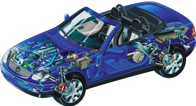
Kompressor-Kaputt In 1998, Mercedes-Benz introduced the SLK (170 chassis) into the United States, a lightweight, nimble, two-seat sports car. Its small size meant it was not able to fit the six- or eight-cylinder engines that were installed in the C280 and C36 AMG models. So, the new four-cylinder, 2.3L (111) engine was used. While this engine is solid, a sports car really should offer more performance than an entry-level C-Class (C230).
The solution to this was the addition of forced air induction in the form of supercharging. In ‘02, the SLK by AMG received a 3.2L supercharged V6, in ’03 the C230 got a 1.8L supercharged engine, and all of the AMG 5.5L engines were “artificially aspirated†as well.
This was not a simple matter of bolting on a blower and some plumbing. Managing boost and minimizing acceleration lag are engineering challenges that the Mercedes-Benz engineers dealt with very well indeed. Here we’ll examine the layout of the supercharging system so that we may better understand how to diagnose it when a problem occurs.
Supercharging 101
Without getting too deeply into the theory of supercharging, we do need to understand the basic principles so we can diagnose a symptom by isolating its cause. Essentially, as an engine rotates through its four cycles it generates a vacuum in the cylinder as the piston drops to BDC. The atmosphere provides outside pressure that is approximately 1 bar or 14.7 psi. This pressure flows toward the vacuum in the cylinder through the open intake valve. At this point the intake valve closes (depending on the camshaft profile and “scavenging†designed into the system), and the piston starts to travel upwards toward TDC, creating the compression. The power produced by the following piston stroke is limited by how much air finds its way into the cylinder during the intake stroke.
By increasing the pressure in the intake system to something higher than 14.7 psi, we can force a greater quantity of air into the cylinder, therefore creating more power. Supercharging achieves this by using the engine’s own power to drive a belt that spins an air compressor. This “kompressor†or “blower†forces higher pressure air into the engines air intake system. This“boost†can produce significant horsepower gains.
There are limits to this phenomenon, however. With too much pressure, the mixture may ignite before the intended time. This pre-ignition (also known as detonation) can quickly destroy an engine. This is why on turbocharged and supercharged engines the compression ratio is reduced. Also, lower octane fuels compound this problem by being easier to ignite. So, there must be some pressure limiting feature built into the supercharging system. A pressure “pop-off†valve can be used, but it is inefficient to waste engine horsepower to drive a supercharger only to blow-off excess pressure that is not needed.
A Tale of Two Paths
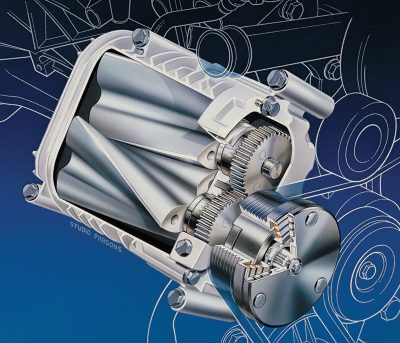
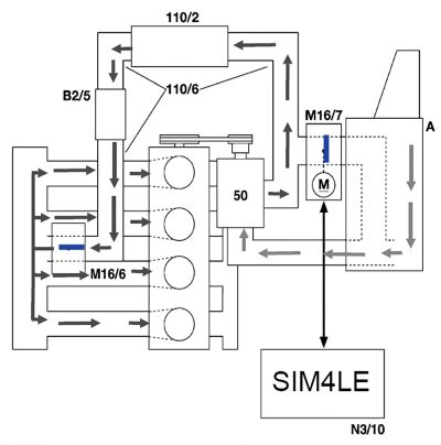
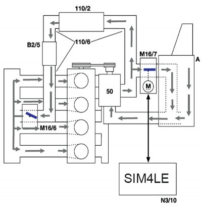
Let’s start by following the air flow of the supercharged 111 engine (2.3L). Of course, a conventional air intake system starts in the air box, which houses the air filter. However, from here we have two different paths the filtered air can take. Under acceleration, it is directed down to the back of the supercharger. Mercedes-Benz uses a “Roots†type blower. Interestingly, Gottlieb Daimler installed this type of supercharger on early production industrial engines 19th century, but, of course, engineering advancements have increased its efficiency tremendously. The Roots supercharger is a positive displacement pump that starts to build pressure at relatively low rpm (about 2,000). It does heat up the pressurized air it produces, though, so the air needs to be cooled by means of an intercooler, which may be of the air-to-air or air-to-water type. The SLK’s air-to-air unit travels along the lower front bumper and resurfaces on the driver’s side of the engine, entering the throttle plate. Later model larger displacement supercharged engines use a air-to-water intercooler, but more on that later.
The SLK uses a “fly-by-wire†electronic throttle or EA (Electronic Accelerator) mounted on top of the intake manifold on the driver’s side. But how does Mercedes-Benz control the boost pressure in the intake system? You have probably noticed what looks like an electronic throttle assembly right off of the air-box. This is indeed a similar assembly, but it has a different task.
The second air path engineered into the system is dependent upon a Recirculating Air Flap assembly. It acts just like an electronic throttle plate except that when it is closed, intake air is forced through the supercharger and pressurized air is sent to the engine’s intake system. If too much boost pressure is being made for the throttle application (determined by monitoring CPS, TPS and MAP sensor signals), the Recirculating Air Bypass valve is opened to allow air to bypass the blower and continue straight to the intake manifold, or to allow boost pressure to bleed off back through the airbox. This reduces the amount of air passing through the blower and reduces boost pressure. The Recirculating Air Bypass assembly is not just open or closed. The ME control unit can vary the position of the valve to maintain consistent boost pressure. This helps reduce lag when changing from deceleration to acceleration. It also reduces boost if the level becomes dangerous to the engine.
On early 111.973 engines, an electromechanical clutch was used, much like an A/C compressor clutch. This would allow the “kompressor†to be disengaged entirely, therefore not generating any boost or causing any parasitic drag at low rpm. Above 2,200 rpm, the clutch is engaged and boost is produced. In 2001, Mercedes-Benz phased out the clutch mechanism, so boost is managed by the Recirculating Air Flap alone.
Okay, Now How Do I Fix It?
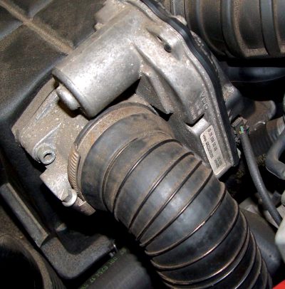
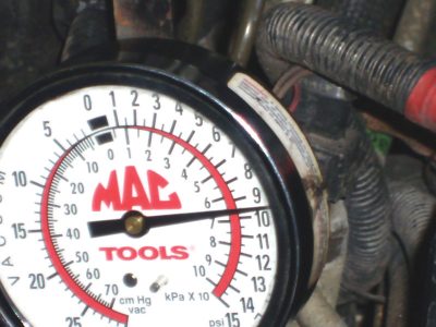
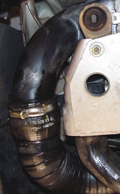
So what are some of the service issues we’re going to face? Let us start with codes. If you pull a code P0805 and/or P1235, then you’re dealing with overall supercharger function. Connecting a pressure gauge to the intake system will tell us if we are achieving proper supercharger pressure. Here in the United States, the 92 to 94 octane gasoline available will not allow any forced air induction vehicle to produce excessive boost without fear of detonation, so boost is limited to just under eight psi. These codes are letting us know that even though rpm, throttle application and load show boost conditions, proper boost is never achieved. This could be caused by a binding Recirculating Air Flap, but more than likely is caused by an air leak in the air intake system. A torn boot or a leak at any plumbing joints will often lead to these codes, which may be accompanied by a driveability problem such as a sudden loss of power, or a “bogging.”
Introducing smoke into the intake system may not indicate the source of the leak since the rubber may only leak when significant pressure is applied. Keep in mind worn or broken motor mounts can add stress to air intake plumbing.
Monitoring boost pressure with a gauge while under load is a good way to determine if boost pressure is being lost — just verify proper operation of the Recirculation actuator.
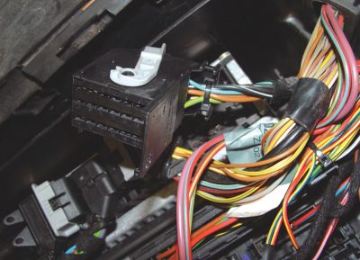
If you pull codes P0806 and/or P1236, they deal with supercharger clutch operation. There is no speed sensor for the blower, so proper operation is determined by monitoring the supercharger clutch electronic signal. You can monitor the voltage and current draw of the clutch and check for proper activation. This is most easily achieved at the powertrain control unit. For example, on a ’98 SLK 230, power is provided to the clutch from fuse F2 in the relay module (mounted in the under-hood, passenger side electrical housing). This fuse also powers up the O2 sensor heaters and the Canister Vent Shut Off valve, so be careful of these other codes. By evaluating the wiring diagram we see that the control unit, connector F, pin 21 is the ground control of the clutch. By monitoring the voltage and amp draw of the solenoid we should be able to determine proper clutch operation and isolate a fault between the clutch and the ECM’s driver.
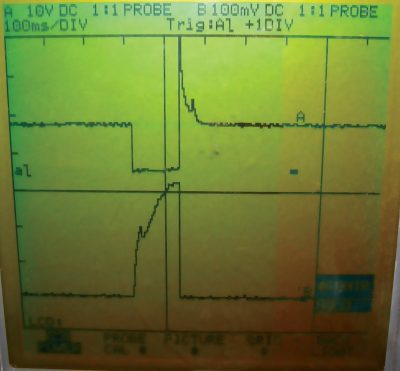
Another set of codes that are part of the forced air induction system are P0803 and P1243. These are for Recirculating Air Flap operation. This actuator is normally open. A pulse-width modulated signal is sent from the ECM to the recirculating actuator commanding it to close and produce boost pressure. As a general rule, the wider the duty cycle (positive slope) of the signal the more the flap is commanded closed. The ECM monitors the boost pressure, throttle angle and mass air flow signals and determines if the flap is working. If you feel comfortable using a dual-trace scope, you should scope the pressure sensor and the flap actuator command signal. As long as rpm is increasing, the pulse width on the command line should increase as the signal voltage on the pressure sensor indicates more boost pressure. If the pressure is dropping while the duty cycle command is increasing, either the actuator flap is malfunctioning, or boost pressure is leaking out of the intake system.
What If I Have A P0410?
On the 111 engine (2.3L), the supercharger doubles as the secondary air pump. This means the supercharger clutch must be activated for 30 to 90 seconds after the vehicle is started to supply the exhaust system with fresh air to aid in heating up the catalytic converters. So, diagnosing a secondary air injection code includes testing supercharger function. Activating the blower clutch and the secondary air control solenoid while at idle should pump fresh air into the exhaust. You can monitor additive (idle) adaptation to see that fuel is being added. Remember to have the fuel system in closed loop so that fuel trim adaptation is functioning. You can also watch O2 sensor voltage to see that it drops to under 100mv indicating a lean condition. How Do I Prevent Costly Supercharger Repairs?
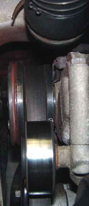
By its design, the Roots supercharger has a non-contact air gap so rotor vanes should not be rubbing together. However, the supercharger assembly does require special lubrication. As per the StarTuned article “Liquid Diet†(archived on the website in the June, 2006 issue), the C230K and SLK230 have their own lubricant, Part Number 000 989 62 01. It is added through the fill/inspection plug hole. The 3.2L and 5.5L AMG engines use a different supercharger lubricant — Mobil Jet Oil II. Also, the 3.2L and 5.5L AMGs have a Charge Air Cooler Circulation pump. This uses liquid coolant to keep the temperature of the supercharger within bounds. As mentioned earlier, the 3.2L and 5.5L engines by AMG use an air-to-water intercooler, so be sure to drain coolant and bleed the cooling system when servicing the intercooler. As with any other belt-driven component, belt wear and proper tension are important.
In Conclusion
While Mercedes-Benz engine management systems are very good at monitoring problems and indicating faults through their self-diagnostic functions, a driveability problem may still need some good old fashioned hands-on testing. Monitoring boost pressure, sensor signal voltage and solenoid voltage control/amperage draw may be the final steps in verifying the cause of the customer’s complaint. Of course, there is always the most important ingredient: a thorough understanding of the system at hand.


0 Comments