
The ASR warning light will illuminate when the system is commanded not to function, either through the “ASR Off†switch, or if there is a fault in the system. When the light comes on while driving, it does not mean there is a DTC in the system. It means there is a problem with traction at that time.
Electronic driver aids have clearly helped reduce traffic incidents over the past decade, but they don’t do much good when they’re not working properly. Keeping our customers’ Mercedes-Benz vehicles functioning in the safest possible manner should be our goal. So, here’s how ABS/ASR and ESP systems work and how to repair them.
Anti-Lock Brake systems (ABS) have been around for decades. In a panic stop, the driver, not being properly trained, applies the brakes as hard as possible. This causes the brakes to overpower the grip between the tire and the pavement. The wheels are now locked and steering inputs prove futile. The driver has lost control of the vehicle.
Using a computer’s high-speed data processing capabilities, however, programming can reduce brake fluid pressure at individual wheels during a panic stop. This allows the tires to continue to rotate and retain grip. Since traction hasn’t been lost, steering control is possible. The computer can reapply the brakes and continue the slowing-down process. This pattern occurs several times a second, gradually stopping the vehicle in a controlled manner.
As in the case of fuel injection, the computer can monitor sensor inputs, look at its pre-programmed set of responses, and manipulate output controls to further enhance the stopping ability of the vehicle. Since a computer can react to these changes quicker than any driver can, braking distances are reduced while steering control is maintained. Believe it or not, this simple explanation can be applied to even the most complicated integrated systems: inputs, logic, and outputs. Knowing how these function together will allow you to test them. This, coupled with an understanding of the computer’s logic, lets you predict and test output controls.
, and the other will be normally closed (NC). You can use the scan tool to watch this input, but a DMM will tell you if the switch contact is poor.")
Here we have the dual output brake switch.
One switch contact will be normally open (NO), and the other will be normally closed (NC). You can use the scan tool to watch this input, but a DMM will tell you if the switch contact is poor.
The Power in Power Brakes
Before we get started on ABS/ASR/ESP, we should discuss BAS (Braking Assist System). This is the power in your power brakes. It is still vacuum assisted, but this simple system adds additional assist when needed. The brake booster is exposed to normal atmospheric pressure on both sides of a diaphragm with the engine off. When the engine is started, manifold vacuum is applied to both sides of the diaphragm. When the driver applies the brakes, atmospheric pressure is applied through a metered orifice to the brake pedal side of the diaphragm. This reduces vacuum to about 11 to 12 in. Hg. This differential in pressure forces the diaphragm to move in the direction of greater vacuum or lower pressure, which would be toward the master cylinder side of the booster. This is normal power assist.
Within a Mercedes-Benz booster with BAS there is a release switch and a solenoid valve. The switch indicates when the brake pedal is released. This switch input is sent to the BAS control unit (often mounted underneath the master cylinder). On later models with ASR or ESP, all of the control units are unified into one ESP/ASR/BAS control unit. Another input (either to BAS or ESP control systems) is the Membrane Travel Sensor. This monitors the position of the booster diaphragm. If it detects sudden movement of the membrane, it knows the brakes were applied suddenly. The solenoid valve (in the booster) is then opened allowing full atmospheric pressure into the brake pedal side of the brake booster. With full manifold vacuum on the master cylinder side of the diaphragm and full atmospheric pressure on the other side, the larger difference in pressure moves the diaphragm with greater force toward the master cylinder, thus increasing braking assist. On smaller engines such as in the SLK230, there is an additional vacuum pump to supply sufficient assist.
The ESP, ASR and BAS Lights Are All On!
Of course, the BAS system will not work if there is a failure with a component such as the release switch, the solenoid valve or the membrane travel sensor. Other outside influences such as the brake switch (not present on the very latest models) can set a code and turn on all of these warning lights. The brake switch on a Mercedes-Benz is a double-throw switch. It has one set of contacts that are normally open (NO) and another that is normally closed (NC). These switch contacts reverse position when the brakes are applied.
Scan data can be used to monitor these switch inputs. To test these switches directly you will probably have to look in multiple diagrams. One brake switch contact could be connected to various control units, such as the illumination module for brake light activation, and the other switch contact could be connected to the Electronic Traction Support module (ETS) on vehicles with four-wheel drive. They could also go directly to the ESP/ASR/BAS module, so make sure you know the system you are working on. One easy way to check which systems are in a particular vehicle is to simply look for the various warning lights coming on in the instrument cluster during the key-on bulb check. In later models, the brake switch input is normally sent to the ESP/ASR/BAS module and is communicated to other control units through the CAN.

Since the control unit is so easy to get to, you can measure the resistance of the wheel speed sensors right from the connector. This not only checks the sensor resistance, but it also checks the wiring. This testing does not apply to Active Wheel Speed sensors.
The Essence of ABS, ASR, and ESP

Some of the most critical components in any of these systems are the wheel speed sensors. They often double as the vehicle speed sensor input and their signals are transferred to the other control units through the CAN. Wheel speed sensors live in a harsh environment. Mounted on the wheel spindle, they are exposed to high temperatures, moisture, road salt and debris, and brake dust. They are AC pulse generators, so when scoped they produce an AC sine wave. This AC sine wave indicates the speed of the wheel. If the frequency of the sine wave increases, then the wheel has picked up speed. If it decreases, then the wheel is being slowed down.
Some models such as the C- and CL-Class in 2001 and the S-Class in 2000 started using what is called an active wheel speed sensor. This has no reluctor or tone wheel, instead using magnets in the wheel seal (be gentle with them during service) to cause magnetic switching and generate a DC square wave. With any of these sensors at each wheel the ABS control unit can determine if any wheel(s) are slowing down faster than any of the other wheel(s) while under braking. This would indicate different wheel speeds, which means some of them are losing traction. The ABS control unit can then isolate the ones that are “locking up,†and reduce and apply brake pressure as necessary to bring the vehicle to a controlled stop.
A second step in assisting the driver is through ASR. If the wheel speed sensors can determine if one or more wheels are slowing down too fast, then it stands to reason that a computer could determine if the wheel was accelerating faster than the others, otherwise known as wheel slip. In the event of this phenomenon, the ASR module can isolate the brake fluid circuit and apply brake pressure (stored in the system) to the wheel(s) that is/are slipping. This is roughly the same action as an ABS stop, but this time the brake is not depressed and the vehicle is accelerating. This is never more evident than when accelerating or decelerating in snow.

This control unit is one of many on the powertrain CAN. This ASR control unit has traction control, but in this ’97 S320 does not have ESP. Notice how easy it is to perform electrical testing at this unit. Under “Diagnostics,” you’re given the pin voltages to test for.
Mercedes-Benz has addressed this problem with Electronic Traction Support. This system can detect wheel slippage between the two driven wheels and apply the brake to provide even power distribution. In addition to brake application, the ASR unit can convey to the ME (Motor Electronics) to close the throttle. This is referred to as Engine Torque Reduction (ETR). The ME control unit can either retard timing, or close the throttle plate to reduce power output. In the case of deceleration, if the ASR control unit detects a difference in rear wheel speed compared to vehicle speed it can request the ME control to open the throttle to reduce engine braking. This is referred to as EBR, or Engine Braking Regulation. As you can see, with the integration of all these systems CAN communication is critical to keeping those warning lights off, so an advanced scan tool such as the Mercedes-Benz Compact III would be a tremendous advantage in this area of diagnosis. Keep in mind there is also an ASR “Off” switch. Switching the system off may help you isolate the cause of problem.
As mentioned earlier, monitoring wheel speed is critical to these systems functioning properly. You need to know how to test these sensors. One of the first steps you should take is to scan the computer for codes. Mercedes-Benz electronic control systems are capable of detecting many abnormalities even if they are minor enough not to warrant illuminating the warning lights. Another step in the diagnostic process is, through our scan tool, monitoring the wheel speed sensors. Of course, during any test drive be mindful of safety, especially while evaluating scan data. It’s best to have someone else drive while you monitor data; perhaps the customer could drive while he or she is explaining to you what he or she feels while driving the vehicle. The scan tool is also useful for checking various switch inputs such as the brake and release switches. If you get to a point where the scan tool has given you all the direction it can, you may have to electrically test each component.
 and ETS. If these lights stay on with the engine running, you definitely have a fault in the system.")
One way to determine what variations are on the system you are working on is to look at the warning lights during a bulb check. You can see that this vehicle has BAS, ESP (which means it has ASR also) and ETS. If these lights stay on with the engine running, you definitely have a fault in the system.
As already mentioned, Mercedes-Benz vehicles will either have AC pulse generators for wheel speed sensors, or Active Wheel Speed sensors, which generate a DC square wave. Even though it’s a square wave, the principle remains the same. The faster the wave, the faster the wheel is traveling and visa versa. With the AC wheel speed sensors you can start off with a resistance test to make sure you do not have a shorted sensor, but it is best to monitor AC voltage while spinning the wheel by hand. Each wheel should produce a similar AC voltage — between .5 and 1.5V, depending on how fast you’re spinning them. Sensors may have different resistances and AC voltage output, so it’s best to compare one side of the vehicle to the other. In the case of the active wheel speed sensor, a graphing multi-meter or lab scope will illustrate the wave pattern. If this is not available to you, a DMM capable of DC V, Duty Cycle and Frequency will allow you to monitor the consistency of the signal. If you detect the DC voltage dropping out, the duty cycle changing significantly, or the frequency changing rapidly, you probably have a bad sensor. Keep in mind that these are three-wire sensors that have a five-volt reference and a ground as well as a signal line.
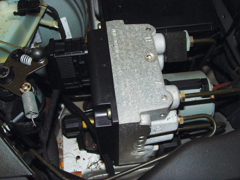
Although you see a control unit-type plug, it is only for the hydraulic solenoid assembly. This component houses the brake fluid
control solenoids. The unit that controls the hydraulic assembly is mounted elsewhere.
Things Are Getting Out Of Control!
To further enhance driver control, ESP was introduced to coordinate the multiple electronic control units. The BAS, ABS, ASR, and EBR make up the ESP system. These systems work together to assist the driver in maintaining control of the vehicle in low-traction conditions. There are a few more components added to ESP to monitor the vehicle dynamics. The first one we will discuss is the Steering Angle sensor. This is often mounted in the steering wheel switch housing. The ESP control unit uses this sensor to compare to the front wheel speeds to verify traction is being maintained. It is a photo-electric sensor that generates a square wave. The shutter wheel that blocks and unblocks the light beam is in a specific pattern, so it is not an even and consistent square wave that you might be familiar with from a camshaft position sensor, or something along those lines.
What is more important is if you replace the sensor or battery power goes dead, you will have to re-initialize the sensor. You can do this with the aid of a factory-specific scan tool, or by slowly rotating the steering wheel lock-to-lock with the weight of the car on the tires and the engine running. There is also a pressure switch mounted in the hydraulic unit. It is a three-wire sensor with a reference, signal and ground. The signal is an analog voltage. This sensor detects brake fluid pressure in the hydraulic unit. Pressure and return pumps in the hydraulic unit create pressure that the ASR system may need to apply to a caliper. Remember, this is for controlling wheel speed under acceleration, not braking.
Other sensors found in the ESP system would be just as at home in an aircraft as an automobile. They are the Lateral Acceleration Sensor and the Yaw Rate Sensor. The Lateral Acceleration Sensor measures the speed of the change in direction of the vehicle. It is a three-wire sensor and has a five-volt reference and a ground, as well as a signal wire. If this sensor needs to be replaced, it must be adapted with a factory specific scan tool. The Yaw Rate Sensor detects the speed of body roll. This is difficult to monitor and is also best diagnosed with a factory-specific scan tool. A problem here could cause the SRS warning lamp to illuminate. You can monitor this signal wire for an analog voltage signal while driving the vehicle through turns. All these inputs go to the ESP control unit, so scan data could make your life a lot easier.
Inputs,…Control Units,… What’s Next?
As mentioned earlier, no matter how complicated the system, it’s just a matter of monitoring computer inputs, knowledge of computer operation, and, finally, predicting and monitoring computer-controlled outputs. We discussed how critical CAN communication is, and checking for codes in all related systems will help direct you to the system at fault. For example, if there is a problem with the Electronic Accelerator, it will turn on the MIL and the ESP system will be disabled since it cannot shut the throttle when it needs to. It’s always a good idea to check all the control units in the powertrain CAN for codes. When dealing with BAS/ASR/ESP, you need to know that the computer controls solenoids to redirect brake fluid pressure according to what is desired. Mercedes-Benz uses Hold, Release and Pressure Apply solenoids in the hydraulic unit.
When dealing with codes, you are usually looking at a wiring problem, or sticking/faulty solenoids that are all incorporated into the hydraulic unit. As well as using resistance checks to test, we can also activate solenoids (preferably through a scan tool) and monitor the current relative to the voltage change.
Overview
We hope you have learned what input sensors are involved in BAS/ASR/ESP. Checking for codes in all Engine CAN control units will give you a diagnostic direction. Monitoring these inputs in scan data can help you quickly determine what system you should be testing. After pulling up a wiring diagram, you can now directly check sensor inputs and monitor computer-controlled outputs that did not respond properly during scan tool testing. This all leads to the isolation and conclusion of a successful diagnosis, no matter how complicated the system. We can all consider this a job well done.


0 Comments