Since the early ‘90s, Mercedes-Benz has developed its Controller Area Network (CAN) to control how components communicate with each other and with us through our Compact III or Basic. How has this evolved, and what does it mean to diagnosis and repair?

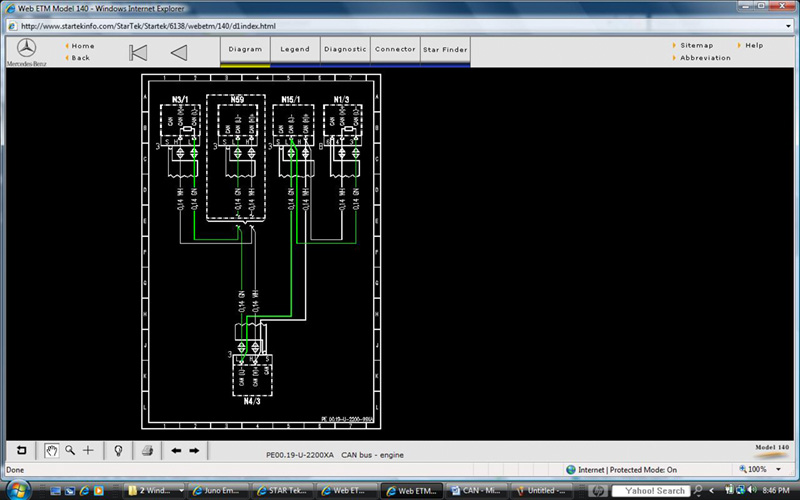
This is a wiring diagram of one of the first Mercedes-Benz CAN systems, including control units for the powertrain. The DI/KSS (N1/3 ignition), LH-SFI (N3/1 fuel injection), CC/ISC (N4/3 Cruise & Idle), TCM (N15/1 transmission) and Diagnostic Module (N59 OBD I) are all communicating on this network.
What is the purpose of advanced technology? What is the downside? Nowhere are these questions more relevant than in the automotive industry. The purpose of technology is to improve the driving experience, safety, and fuel mileage, and to reduce harmful pollutants. The downside is ever more complex systems. When things are working as designed, fine. But, as the saying goes, “To err is human, to really foul things up takes a computer.”
Computer-controlled systems have expanded their role in modern vehicles. This has allowed for such advancements as Motor Electronics (ME), antilock braking systems (ABS), electronic accelerator (EA) systems, and so on. The evolution of these various systems led to their integration. Coupling wheel speed inputs from ABS and throttle position sensors from ME determines wheel slip under acceleration, and this slippage can be controlled by applying braking force to a particular wheel and/or by limiting power by means of the EA. This integration results in Anti-Slip Regulation (ASR). Include in the equation computer-controlled suspension and you have the Electronic Stability Program (ESP).
In later years, this integration has expanded to include all computer-controlled systems. Body controls need to talk to one another during certain functions. On convertibles, for example, the door control units need to be informed that the top is being opened so it can lower the windows slightly to eliminate interference with the top. By pulling on the door handle, the central locking system also informs the door modules that the door is being opened so the windows can be opened enough so that they don’t rub against the door seal.
As well as talking with other body control units, these computers may have to talk to powertrain control units. We wouldn’t want someone opening the convertible top while driving at 60 mph. The ABS/ASR control unit must pass on the vehicle speed to the body system control units to prevent unsafe operation.
To save weight and wiring complexity, control units have been strategically placed throughout the vehicle. However, testing something as simple as brake light failure has become complex. In some instances, the brake switch input goes directly to the ABS/ASR/BAS (Braking Assist System)/ESP modules. If each control unit that needed it had its own brake switch you would need one for the brake lights, one for the ABS/ASR, one for the cruise control, etc. But there are only two brake switch inputs. How is the lighting control module informed to turn on the brake lights? The signals get on the CAN (Controller Area Network) bus.
The Bosch bus
Separate computers need to communicate with one another to perform these integrated functions. In Mercedes-Benz vehicles, the computers communicate through a CAN. Robert Bosch developed this form of serial communication starting as early as ’83, and a commercial version was available in ’86. Mercedes-Benz was there during the development phase of the CAN protocol. Serial-type communication means messages (in our case, 11 bit or 29 bit) travel over a single wire. Parallel bus communication, on the other hand, means each bit needs its own wire to travel down from one processor to another, which would result in a lot of extra wiring. Serial communication is what’s used in a network of PCs.
Analog or digital inputs are processed by a control unit for its own use. The unit then generates bus communication through square on/off signals. If another control unit needs some or all of the information on the CAN line, it determines what information it needs and uses it for its operation and its output controls. This control unit may also have inputs it puts out on the CAN for the use of other control units. All control units in any particular network can share information via the CAN.
What if the CAN were to “go down†and not transmit information? The control units could not communicate and needed information would be lost. Most functions requiring inputs from multiple control units would not work. This would include something as basic as starting and running the engine. Without the Drive Authorization System (DAS) approving the ignition key, the ME control unit will not allow the vehicle to crank and/or run. So, these networks must be kept up and running for the vehicle to perform as the Mercedes-Benz engineers designed it, with all of its safety features and creature comforts.
We need to have a diagnostic plan for when control unit communication is lost. We will need to know the pathway of CAN communication and how to test these signals. What often surprises automotive technicians is how simple these systems are to diagnose. Mercedes-Benz SDS
software, through the use of a Compact III or Basic, is very good at isolating communication problems. This is due to the design of the CAN protocol through error handling, bit timing and synchronization.

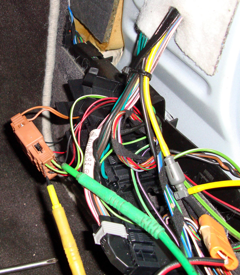
Locate the bridge connectors under the carpeting and interior molding, and you can test voltage signals. Unplug suspect control units and verify there is no corrosion from moisture, coffee, soda, etc. In this case, you can unplug the connector to isolate the ME control unit.
CAN Protocol
Mercedes-Benz vehicles can have multiple Controller Area Networks. For powertrain systems, these may include:
- ME Motor Electronics
- ETC Electronic Transmission Control
- ESM Electronic Shifter Module
- ESP Electronic Stability Program
- SAS Semi Automatic Suspension
- CGW Central Gateway Module

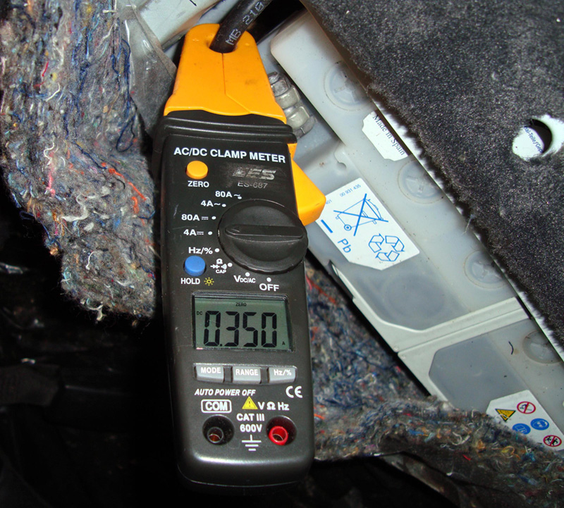
When testing for battery drain, look at amperage draw after the vehicle has been shut off for several minutes to be sure all the control units have gone to sleep. The normal procedure of unplugging fuses to locate the draw must be augmented by unplugging control units from the CAN for the same purpose.
Mercedes-Benz CAN protocol is sent out on a two-wire twisted pair integrated into the wiring harness. One wire carries the CAN High signal and the other carries the CAN Low signal. The CAN High signal starts off at .65 volt when it is at ground, and the square waves rise to about 2.5V. The CAN Low signal starts off communication at 4.65V when high and 2.5V when low. The two signals are identical in so far as square waves are concerned, except that one signal switches high (CAN High) and the other signal switches low (CAN Low). If you were to scope both signals on a dual-trace lab scope, they would appear to mirror each other. If a condition existed that interrupted either the CAN High or Low signal, an emergency mode would take over and the computer would communicate over the CAN line that is still functioning and set fault codes in each control unit on that particular CAN. If both CAN H and CAN L lines are shorted to power or ground, communication would be lost among all control units on that CAN

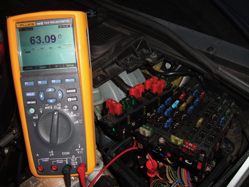
To see if the CAN
lines have an electrical problem with the wiring you can get access to the CAN lines (there under the fuse box in a 140 chassis) and measure resistance between CAN low and CAN high. Since there are two terminating resistors in the circuit in two of the control units you should measure about 60 ohms.
The wiring among all the control units is wired in parallel. This means each control unit receives the same CAN High and Low signal. In 1992 on the 140 chassis, the CAN wires were spliced together at each control unit. If you are going to test the CAN, you will need to get to a control unit on the engine CAN, otherwise known as CAN C. There is a terminating resistor on this CAN line. If you were to unplug the LH-SFI (fuel injection), or the DI/KSS (Direct Ignition) control units and measure resistance between the two CAN wires at that connector, you would read approximately 120 ohms. When unplugging either the CC/ISC (Throttle Module), Transmission Control Module (TCM), or the Diagnostic Module and checking resistance between the two CAN wires, you should read approximately 60 ohms.
Remember, only one control unit at a time should be unplugged to perform this test. These control units are difficult to scope for the CAN H and L signals since the connector faces down and the splices are underneath the control units in the housing.
Starting around ’96, the CAN wires were spliced together. On the wiring diagrams these splices are named “Z†splice packs. Also in ’96 on the newer chassis, bridge connectors are used to link the CAN wiring. This can prove helpful when diagnosing CAN communication problems that are the result of problem wiring. We can access the CAN directly at several different areas where these splice packs or connectors are located. We often try to go to the easiest point we can access.
Mercedes-Benz uses multiple CANs. The powertrain CAN is CAN C. The Body CAN is CAN B. The diagnosis CAN is referred to as CAN D. There can also be a MOST bus, but that is a fiber optic network that we will cover in another article. When evaluating communication problems between control units, you should find out which ones are on that particular CAN, and, using your Compact III or Basic, try to communicate with each control unit that is connected. You should be able to communicate with each unless the bad control unit is shorting the CAN lines to power or ground. A control unit that is simply not responding will not bring down communication on this CAN. The reason is that the computers all wait for an empty CAN transmission line and then put out the information that has changed. Other control units wait and only pick up the information they need out of the transmitted message. The original message is still on the CAN and can be picked up by other control units.
If in the event the CAN is down, you will need to start disconnecting control units to see which is at fault. With all the control units on a particular CAN, this can be time-consuming. Find the bridge connectors for the CAN, typically labeled X30/#. These connectors are usually located at the base of the “A†pillar below the passenger’s and driver’s side kick panels. If the doors are not properly sealed and water gets into the cabin, corrosion can interfere with digital voltage communication signals. When accessing these connectors, check for moisture in the area.
Other Possible Problems
A breakdown of CAN communication among control units is not the only problem that can occur. CAN communication requires electrical power. If these control units were to actively communicate with the ignition key off, the
current draw would discharge a battery. Overnight, your customer might wake up with a dead battery even though nothing was left on. With the ignition off, control units no longer need to communicate as much information so they slow down. Also with the ignition key off, either the EIS (Electronic Ignition Switch) or the CGM (Central Gateway Module) senses this and sends out signals to put control units into a “sleep†or power-down mode. The Central Gateway Module is often mounted under the instrument cluster on the lower panel by the driver’s feet. This control unit is in charge of managing the different CAN messages between different CANs. This allows information on CAN C to be passed on to CAN B, and so on. Previous to the introduction of this module, the EIS was the gateway and managed CAN communication. Putting the control units to sleep reduces current draw to under 50 ma, which is low enough to not kill a battery even after several weeks. As mentioned earlier, the CAN H signal oscillates between .65V and 2.5V, and CAN L oscillates between 4.65 and 2.5 volts. When the control units go to sleep, the CAN voltages change. CAN H drops to .025V and CAN L increases to 11V. These voltages are maintained for the duration of the sleep period. The voltage may seem high, but the current draw is very low.
If any control unit were to continue transmitting digital messages, the EIS or CGM would not request the control units to go to power-down and the vehicle’s battery would discharge. You can check voltage or scope the signals and see if the CAN lines power down. You will still have to access the splice connection and bridge connectors to unplug each control unit’s CAN wiring until the CAN goes to sleep. After unplugging a control unit’s CAN wiring, wait a few minutes before checking the CAN signals or voltages.
In conclusion
Communication problems are not that hard to diagnose. Thanks to the engineering and design of the CAN protocol, you should still be able to use your Compact III or Basic to communicate with all the control units on the CAN until you find the one that’s “incommunicado.” Very often the other control units will have diagnostic trouble codes indicating the control unit is not communicating. In the event that one CAN line is down, it can communicate with the other CAN line. You can test the resistance of the terminating resistor, and unplug splice packs and bridge connectors to isolate faulty wiring. The use of a scope or voltmeter can establish if the CAN is powering down, and unplugging bridge connectors will isolate the control unit that may be at fault.


0 Comments