It’s the single most useful technique there is for electrical circuit diagnosis.
Voltage drop testing allows you to examine how a circuit is really performing while it’s energized, rather than simply guessing how it might perform before a switch gets flipped.
Effective electrical diagnosis is nearly impossible without a solid understanding of voltage drop testing. The time you spend learning or reviewing this technique will surely be repaid – with interest – in the time you save diagnosing your customer’s Nissan or Infiniti.
What it is
A voltage drop is the difference in voltage measured between two test points in an energized electrical circuit. Or, you could think of it as the amount of voltage “used†by a segment of a circuit.
As with all voltmeter testing, measurements are taken by placing the voltmeter probes in parallel with the section of the circuit you want to measure. The points of measurement can be both on the positive side of the circuit (before the load), both on the negative side of the circuit (after the load), or one on the positive side and one on the negative side (across the load).
Measuring voltage drop differs from measuring voltage potential because voltage drop measurements are taken while the circuit is energized. Current must be flowing in the circuit in order to do a voltage drop test – the switch, relay, driver, or whatever is controlling the circuit must be closed to do voltage drop testing – otherwise, you’re just measuring voltage potential.
Why do it?
You perform voltage drop testing to determine whether the circuit loads are receiving enough voltage to operate properly. If they’re not, you can “divide and conquer†to determine how much voltage each section of the circuit is consuming in order to determine why the loads aren’t receiving adequate voltage.
In an ideal circuit, all of the voltage is used by loads, and little or no voltage is used by the parts of the circuit that aren’t loads. So, what is – and what isn’t – a “load?â€
- A load is any device that uses voltage to perform some type of useful work. In the context of an electrical circuit, this means that electrical energy is changed into some other type of energy.
- For example:
- Electricity supplied to a motor is changed to torque and heat.
- Electricity supplied to a solenoid is changed to linear force and heat.
- Electricity supplied to a control unit is used for sensor and actuator logic, and ultimately changed into motion and heat.
- For example:
Wiring, connectors, switches, relay contacts, and crimp joints are not loads. Even so, they do consume some voltage. These parts of the circuit don’t do any productive work themselves – any voltage they use robs the loads of the voltage they need to work properly – so it’s best if they use as little voltage as possible.
Energy never disappears; it just changes from one form to another. If a connector is using power, you may wonder, “Where is it going?â€Â The answer is: the power is being converted to heat. This heat provides no benefit. On the contrary, the heat generated by an unwanted voltage drop can be destructive. For instance, a loose pin fit in a connector may result in the connector housing melting.
Voltage drop testing is an excellent way to determine how much of the supply voltage the electrical loads are using, and how much voltage is being used on the way to and from the loads.
When a good circuit goes bad
Voltage drop is created by resistance to current flow. The “garden hose†analogy helps to explain this.
Imagine a garden hose with a lawn sprinkler attached to the end (the sprinkler is the load in this example). Water is flowing through the hose and out of the sprinkler.
If you pinch the garden hose with a pair of needle nose pliers to block some of the flow, what happens? The pressure on the faucet side of the pliers will be very high.
You could test this by trying to squeeze the hose. The high pressure will make it difficult or impossible to collapse the hose with your fingers. Since voltage is electrical pressure, you can expect to measure a high voltage on the positive side of a resistance.
The pressure on the sprinkler side of the pliers will be low. If you squeeze the hose with your fingers, the low pressure will make it easier to squeeze. Once again, since voltage is electrical pressure, you can expect to see lower voltage on the negative side of a resistance.
Voltage drop is measurement of the difference in voltage between one point in a circuit and another point in a circuit.
Marshall your forces
There are two necessities for voltage drop testing – a wiring diagram and a voltmeter. Grab the diagram first.
Understanding how the circuit you’re testing should function is the first step. Sometimes proper circuit function will be obvious when you look at the diagram. Other times, you’ll need to read the circuit description in addition to looking at the diagram.
Regardless, know what you expect to see at any given test point before reaching for the meter. It may occasionally seem like you are spending too much time researching the circuit, but taking the time to understand and plan your attack before you start “working” will result in a faster diagnosis overall.
If there’s no system description available for the circuit you’re testing, but there is a diagnostic flow chart, look at the wiring diagram, then completely read the flow chart, taking the time to consider the reasoning behind the tests it shows. This will reduce the likelihood of misunderstanding any of the tests or their desired outcomes, and will give you the opportunity to verify a failure by using more than one test – always a good idea.
You’ll find everything you need to understand your circuit on the Nissan Service Information web site (http://www.nissan-techinfo.com), or the Infiniti Service Information web site (http://www.infiniti-techinfo.com).
The circuit diagrams, system descriptions, connector views, harness layouts and locations of all kinds are easily accessible on these web sites. You can print what you need, or bring your laptop to the car with you for reference.
Major meter
The voltmeter is often the only piece of electrical test equipment you’ll need to make an accurate electrical diagnosis. Although there are many differences that make some voltmeters easier to use than others, there’s one requirement for any meter you plan to use: it must have adequate impedance.
Impedance is the meter’s resistance to current flow. In voltage drop testing, the connection of the meter should have no effect on the circuit being tested.
A meter with low impedance may cause excessive current flow when it’s connected. If it’s used on a circuit with sensitive electronic components, they can be damaged. Most digital meters have adequate impedance (look for 10 megohm in the spec sheet). Analog meters rarely have adequate impedance.
A voltmeter is always connected in parallel with an electrical circuit. This means that current has a “choice†of flowing through the circuit or through the voltmeter. Since the resistance of the voltmeter is very high (10,000,000 ohms or more), very little current flows through the meter, leaving the circuit to operate in the same way it would operate without the voltmeter connected.
Keep the ohmmeter away from the fray
Many of you will know that electrical resistance is measured with an ohmmeter. So, if resistance to current flow is what causes voltage drops, why not test for resistance with an ohmmeter instead of using voltage drop testing?
The answer lies in the amount of current flow. An ohmmeter works by pushing a tiny amount of current through the component being tested – usually much less than a milliamp at a very low voltage.
This tiny trickle will easily flow through many restrictions that would resist flow when operated at their normal current level. The higher the level of current flow in a circuit, the less useful your ohmmeter becomes.
A circuit designed to draw a lot of current will have thick heavy gauge wires. Have you ever really considered why? When a large amount of current is pushed through a small gauge wire, the wire will act as a resistor; voltage will drop across the wire as a result. To make matters worse, current through a resistance will create heat, which will increase resistance, and cause an even greater voltage drop.
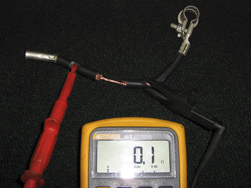
Take a look at Figure 1. This is a negative battery cable with some of the wire strands removed to reduce the gauge of the cable in a small section.
The insulation has been stripped away on either side to allow an ohmmeter to be attached in parallel to the injury. Notice that the ohmmeter is reading near zero? This cable is OK so far as we can tell with the ohmmeter.
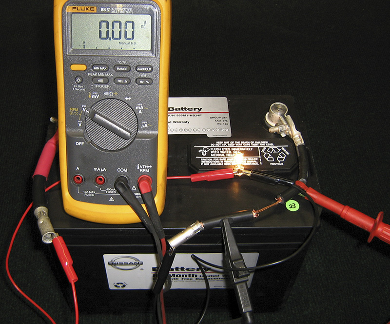
In Figure 2 we tested the voltage drop while the cable was powering a small 5W light bulb.
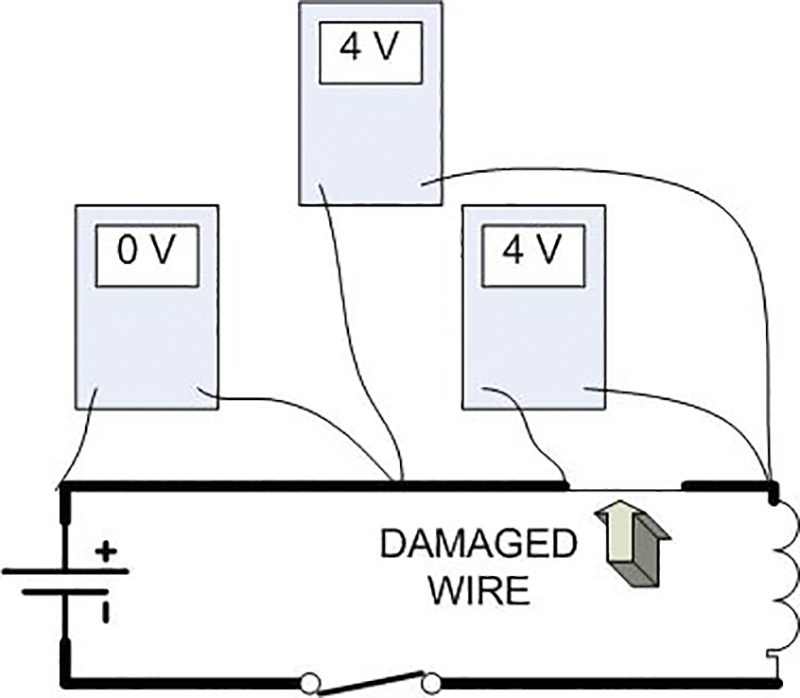
The meter is reading 0 volts, which means there is no voltage drop across the section being measured. This is excellent, since the cable is not a load, and in an ideal circuit, we would only see voltage drop across loads. The cable still looks like it’s OK.
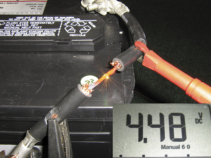
However, look what happens when we use a carbon pile to simulate the load of a starter motor. (Figure 3) The voltage drop starts to climb as soon as the load is increased. As you can see in the picture below, the wire gets red hot; the voltage drop increases radically once the circuit is loaded.
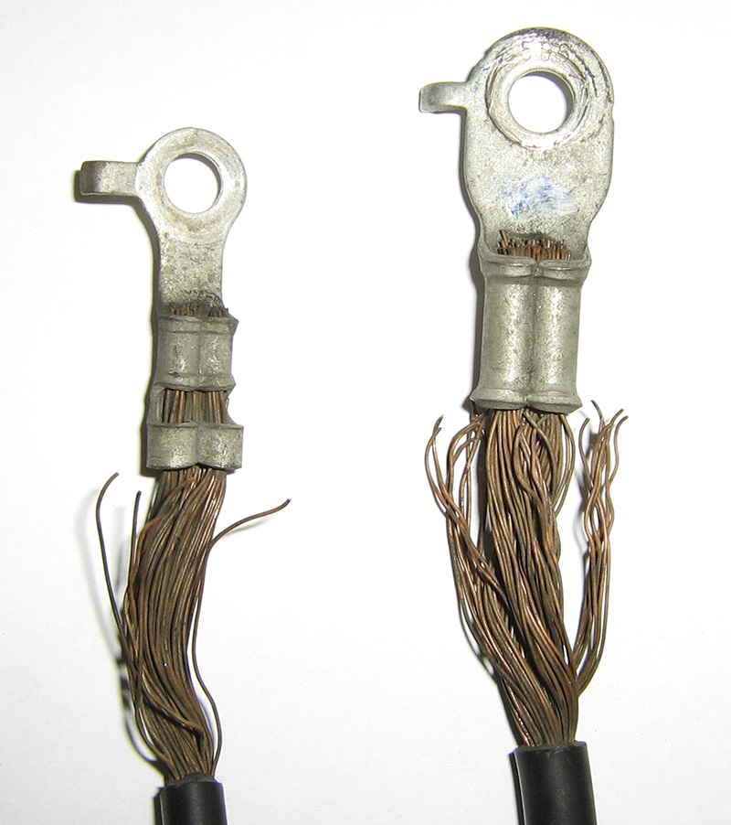
It’s unlikely that you’ll find a customer’s car with a battery cable modified like this one, but it’s common to see frayed battery cables (Figure 4) and ground straps, or loose or corroded battery terminals, which all amount to the same thing.
Cars with bad motor mounts or missing battery hold-downs often develop breaks in the cables where they’ve been flexing. Voltage drop testing is the only good method of testing battery and alternator cables because of the heavy current loads they carry.
Always go with the flow
Because voltage drop testing relies on current flow to work, testing an open circuit provides no useful results.
Let’s go back to the garden hose example for a moment. If we cut the hose about a foot before the sprinkler, then plug it with a cork, water flow will be completely blocked. Since an open is infinite resistance to flow, this is the water hose equivalent of an open circuit.
Now, if we pinch the middle of the hose with needle nose pliers again, what will the pressure difference be on either side of the pliers?
If the faucet were open, the hose would be hard on either side of the pliers — there would be no pressure difference / no voltage drop. If the faucet were closed, the hose would be soft on both sides of the pliers — there would still be no pressure difference / no voltage drop.
This is exactly what will happen on an electrical circuit. If a fan motor circuit is switched on the ground side, and the switch is open, performing a voltage drop test from the positive battery terminal to the positive terminal on the motor will show 0 volts.
No voltage drop, but does that mean there’s no resistance on the positive side of the circuit? Not at all. As soon as we close the switch, current will flow through the resistance, and voltage will drop across the resistance. In other words, now that the circuit is completed (no opens), voltage drop test results will be useful.
This is not to say a voltmeter can’t be used for diagnosis on an open circuit; it can. For instance, an open circuit could be found by following the circuit with a voltmeter until the voltage went from high to low. However, any areas of high resistance could not be found until the open circuit was repaired and current was flowing again.
Stay connected
Never unplug any component or connector prior to testing. This may be obvious to you, given that current must be flowing to do a voltage drop test, yet unplugging a component before checking for voltage is such a common mistake it bears mentioning.
If you unplug a fuel pump connector, and measure 12.7V on the harness connector, does that mean the fuel pump is getting
adequate voltage when the circuit is energized?
Since any resistance in the circuit will not drop voltage until current is flowing, and current can’t flow until the fuel pump is plugged back in to complete the circuit, the only thing you’ll know from this test is that there’s not an open circuit; so don’t wait until after you’ve replaced the fuel pump to test the voltage drop across the pump with the pump plugged in and the circuit energized.
Divide and conquer
As we stated earlier, the first step in voltage drop testing should always be studying the circuit. Even if you’ve already memorized the wiring diagram, it still might be a good idea to give it another look.
Deciding where to test first depends on two considerations:
- Where the circuit can best be divided into two equal parts
- How accessible the desired test points are
Asking the following questions will usually lead you in the right direction:
- What load is not performing properly?
- Can I access it easily?
- If access is difficult, where is the closest test point that’s easily accessible?
Where to start?
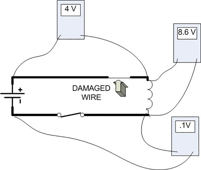
Testing voltage drop across the load is usually the best place to start. In Figure Five, the drop across the load is 8.6 volts.
Since the primary objective of voltage drop testing is to determine whether the load has adequate voltage to operate, this one test may be all you need to complete the diagnosis.
If the load has adequate voltage, and it doesn’t operate, the component (load) is bad, and needs to be replaced. You’re finished with the diagnosis, and can move on to other work.
If the voltage at the load is inadequate (as it is in this example), you’ll need to find out why. The quickest way to do this is to check voltage drop from the positive battery terminal to the load, and then from the negative battery terminal to the load.
Divide and divide again
Once you’ve determined whether the drop is on the positive side or the negative side – or a combination of both – you can begin to narrow the location of the resistance further.
The voltage drop in this example (Figure 5) is on the positive side of the load. This is what you’re likely to find most of the time. Since today’s automobiles use a negative ground system, most of the potential trouble points – relays, connectors, switches, crimp joints, etc. – are all more common on the positive side.
That being said, never assume. The ground side of the circuit is every bit as capable of causing problems as the positive side, even though it may not seem as likely to do so.
Once you’ve determined whether the voltage drop is on the positive or negative side of the load, the best way to find its cause is to split the section you’ve tested in half, similar to what you did by dividing the circuit in the first place.
You could, as an alternative, isolate the voltage drop by leaving one lead connected to the positive terminal, then moving the other lead to each test point in sequence, but chances are it would take longer this way.
To divide the positive side, connect one lead to the positive terminal and the other lead to a test point roughly in the middle of the positive side of the circuit.
Which test point you should choose will also depend largely on accessibility. You won’t save time by dividing the circuit evenly if you must remove the dash to do it.
If you have no voltage drop on the first half of the positive side, move on to the other half. Continue to divide sections in half until the source of the voltage drop is found.
Testing sequence in starter and alternator circuits
The starter and the alternator will both cause the available battery voltage to change substantially – the starter due to its heavy current input, and the alternator due to its heavy current output.
For these reasons, the sequence for voltage drop testing on a starter or alternator circuit differs from testing other circuit loads. It’s best to start testing them by checking the voltage drop on the positive side and then the negative side.
If you were to start by testing across the load, as in our previous example, you’d need two voltmeters, one across the battery and one across the load. Starting your tests by dividing the circuit is just as quick, requires less equipment, and provides additional information.
Acceptable losses
Please remember the primary objective of voltage drop testing as you consider these specifications below:
- Wire with no connectors 0.001V or less
- Switch 0.3V or less
- Ground connection 0.1V or less
- Positive battery cable 0.5V or less
- Negative battery cable 0.1V or less
- Alternator B+ cable 0.5V or less
Your chief concern should always be whether the load has adequate voltage to operate properly.
If a wiper/washer switch has 0.6V drop, and the wiper/washer motor has a 13.0 volt drop, and doesn’t spin, the motor’s the
problem, not the switch. Might the switch be considered bad? Maybe, but it’s certainly not the cause of the wiper/washers not working.
By focusing on whether the load has adequate voltage rather than a militant application of “rules of thumb†you’ll be able to provide your customer with superior advice.




0 Comments