One of the convenience features used most by your customers is the central locking system. Years ago, M-B took a completely different approach to this by making it pneumatic instead of electrical
Mercedes-Benz vehicles have always had some unique features. Along with reliability, longevity, safety and performance, they’ve helped make these engineering masterpieces some of the most sought-after vehicles in the world.
One unique feature introduced in the 1960s is the pneumatic central locking system, which, as the name implies, does not use the electro-mechanical actuators other manufacturers employ. Instead, it uses a combination of vacuum and pressure to move the door lock actuators quietly and dependably. It has withstood the test of time and continues to this very day. As with any unique system, however, there is a certain level of familiarity that is necessary in order to diagnose and repair the system.
Historical Perspective
The earliest reference we can find to pneumatic central locking in Mercedes-Benz archives is from over 40 years ago. Back then, engine intake manifold vacuum stored in tanks did the locking, but the system soon evolved to use combination vacuum/pressure pumps to supply the force needed. From 1983 onward, the change from vacuum to pressure is accomplished by electrically reversing the rotation of the motor — negative control voltage for vacuum, positive for pressure. Previously, this had been done by means of a switching valve. A typical pump, by the way, should produce .5 Bar (7 psi) within two or three seconds. Pressure in the system is relieved in 15 to 20 seconds after the pump stops. If there’s a heavy leak, the electronics that control it switch it off in 25 to 60 seconds.
Since about 1986, most M-B cars have had what’s called the “multi-point” (also called “3-Point”) system. If you’re not sure what you’re dealing with, go to the passenger’s door and unlock. If all the other doors do the same, you’ve got multi-point. If not, either you’re working on a car with the older single-point system (which unlocks only from the driver’s door), or there’s a problem. But since you’ve been presented with a complaint about this feature, you may be unable to get any action out of it whatsoever. That means you’ve got to dig deeper.
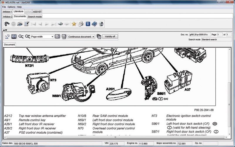
With a paid subscription to www.startekinfo.com, you have access to WIS (Workshop Information System), which will allow you to pull up an operational schematic of the central locking system. This shows all the components involved in commanding the PSE module to lock/unlock the doors.
Around 1990, IRCL appeared, which meant the locking function could be operated by either the door lock switches, or an infra-red remote. The PSE (Pneumatic System Equipment) module received all of the inputs and outputs to command the door locks. By ’96, the door switch contacts were eliminated, and the RCL (Radio Central Locking) module took control.
The integration of central locking with anti-theft and remote control systems evolved as the years went by, and is quite complex with dozens of variations. Since a magazine article cannot possibly provide all the details, you will definitely need www.startekinfo.com, and WIS for specific information on the model at hand. Here, we will cover the basic principles and significant additions to give you a roadmap. We’ll offer one quick tip, however: If the vehicle has an EDW alarm system, you can disconnect the intermediate plug of the EDW cable harness from the connector (M14/1×2, or M14/2×2) and connect the central locking cable harness directly to the supply pump. If central locking works okay now, it’s time to delve into the EDW.
PSE Modern System Operation
At the heart of the central locking system is the pneumatic control unit, which is in total control of the pneumatic portion of the system, and the vacuum/pressure pump is mounted inside it. It also plays a role in operating the Closing Assist (CA). The PSE module is usually mounted under the rear seat on sedans and in the trunk on smaller coupes. As the PSE module evolved, so have its inputs — more than just direct switch inputs command it.
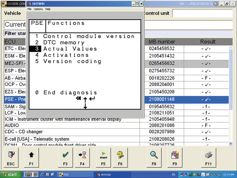
Your Compact III or basic scan tool can access
data that includes version identification, diagnostic trouble codes, actual values, actuations and coding.
This is an excellent way
to check multiple switch inputs, even those from other control units, without having to test each
individual circuit.
Nylon hose is used to connect all of these components and route vacuum and pressure throughout the central locking and closing assist systems. These hoses direct vacuum/pressure from the PSE module to the individual door lock actuators. They have a single port on one side of a diaphragm. Supplying vacuum to it moves the actuator to either the lock or unlock position. Supplying pressure to the same port does the opposite. As you can imagine, this needs to be a “closed†system. Any leaks can cause malfunction.
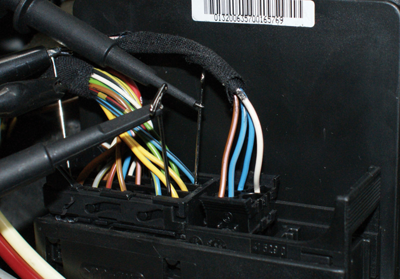
By monitoring the SN1 and SN2 signals, you can evaluate the command to the PSE module to both lock and unlock the doors. You do not need to use an oscilloscope to monitor these signals. A DMM will work fine. You are looking for a 12V signal on each of these wires.
As mentioned, from the early ‘90s the PSE module received all of the inputs and outputs to command the door locks. Starting with the early versions, one of the basic commands to be seen by the PSE module are those from the left and right door switches, which are within the pneumatic actuators. Rotating the key in the door lock or actuating the lock button atop the door signals the PSE. There is one switch contact for the lock command and another for unlock, and they are wired together with the trunk lock switch. Any of these inputs can switch the signal voltage of the PSE module to ground. When the module sees this, it will either lock or unlock the doors. There are other switched inputs, but most of them are for determining door and trunk latch positions.
Later PSE modules have self-diagnostic capabilities. It can store codes and data even with systems as far back as HHT, which is incorporated into the Compact III SDS system. You can see multiple switched inputs at a glance. You can monitor the lock and unlock command switches in each individual latch, trunk tumbler, trunk lid position, individual door position and interior CL switches. Since there can be variations depending on vehicle options, the PSE module needs to be version coded if replaced. Some vehicles have CA (Closing Assist), others have RCL (Remote Central Locking) or CF (Comfort Lock system) options.
If the vehicle is equipped with Infra-Red (IR) remote controls, there are some differences in the way the system works. The basic door lock/unlock switch signals are supplemented with door switch commands referred to as SN1 and SN2 signals, which originate in the Remote Central Locking (RCL) module. Either can command the doors to lock/unlock. By ’96, the door switch contacts were eliminated. The RCL has taken over for these manual controls. This means the RCL is in control of the door locks and the signals to the PSE module have to be tested in order to determine if the PSE is working. These SN1 and SN2 signals are also passed on to the ATA (Anti-Theft Alarm) system to confirm that an acceptable remote opened the doors before the engine is allowed to start (as of ‘98 with SmarKey, engine starting is a seperate function from CL and ATA). Knowing this can be helpful in diagnosing the PSE function if it is not working. Open the driver’s side window, close the hood, trunk and all the doors. Allow the vehicle’s alarm to arm itself. Then, use the remote to open the doors. If the doors do not unlock, reach in through the window and try to start the engine. If it starts, you know the RCL signal made it to the ATA module and therefore must have made it to the PSE module. The module should have unlocked the doors. If the engine does not start, you may have a problem with the RCL system. Monitor the voltages on SN1 and SN2 and see if the 12V signals get pulled to ground for either the lock or unlock command.
A later evolution of the system is the Convenience Feature (CF). This integrated the operation of many body controls into one control unit, including power windows, power door locks and power sliding pop-up roof. The CF control unit directly controls the windows. Door locks are still controlled by the PSE unit, but it receives commands from either the door switches or the CF control unit. After ’96 when the door switches were eliminated, the Drive Authorization System (DAS) radio frequency/Infrared (IR) control module took over commanding the PSE unit to operate the power door locks.
Another feature closely related to the PSE system is Closing Assist (CA), which uses its own separate control unit that is referred to as the CA supply pump. It is only used for locking, not for unlocking. The goal is to continue to close the door all the way after latch contacts the door jamb. A door micro-switch indicates when the door is almost closed and this signals the CA system to supply vacuum/pressure to the CA actuators in the door latch assemblies.
Testing the System
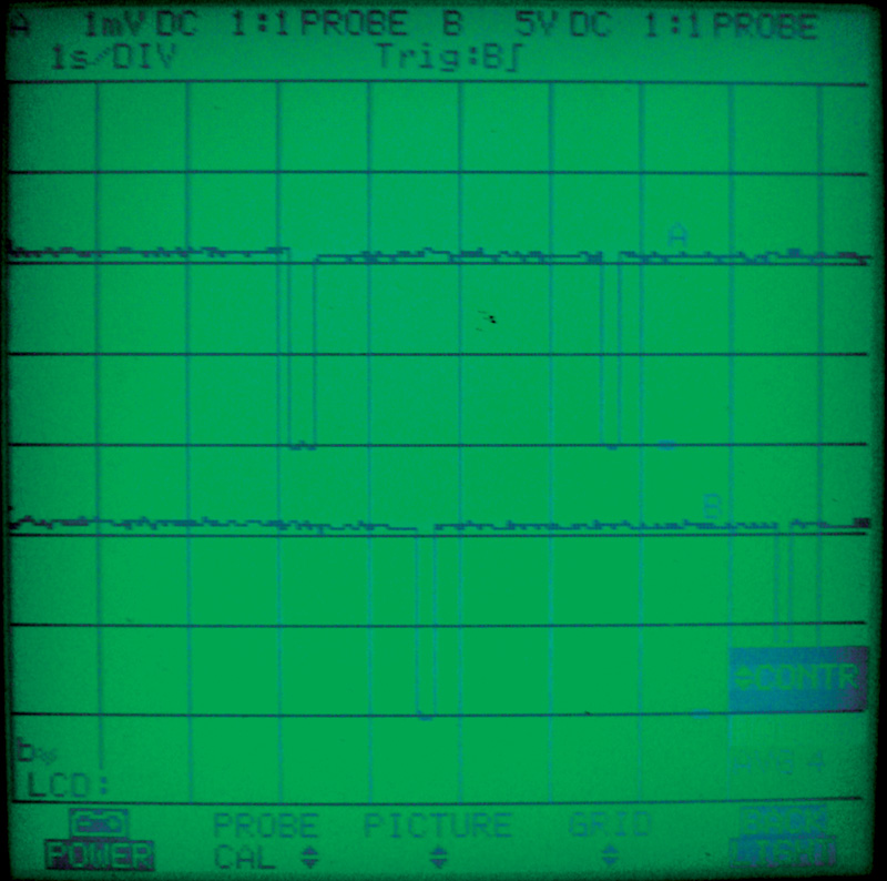
Looking at these signals on a dual trace scope allows you to see the lock command (upper trace) and unlock command (lower trace). As you can see, the 12V signal gets pulled to ground when the door locks are actuated, in this case by the RCL unit as the remote button is pushed to open and close the doors. The signals are there, but the pneumatic pump did not turn on. At this point, check for powers and grounds to the PSE unit. If they are good, replace the PSE module.
If the pneumatic central locking system is not functioning properly, one of the first steps is to find out if there is a problem with the pneumatic system — the vacuum/pressure pump, nylon lines, or any of the three to five actuators — such as a leak, binding, or seizing. This can be done fairly easily at the PSE control module. You will notice a single large line coming out of the module and feeding one of two separate vacuum distribution hubs. The yellow one supplies both vacuum and pressure to the smaller yellow lines, which are the individual vacuum/pressure supply lines for the actuators. By removing this line and connecting a vacuum/pressure gauge, you can see if the pump is capable of generating the necessary vacuum or pressure. If the pump is okay, move on to the lines and actuators. If there is a vacuum leak here, none of the door lock actuators will move. If only one actuator will not move it could simply be bad, seized or leaking actuator, or its hose may be leaking or crimped. There are check valves throughout the system to isolate the problem line. Because of the way the lines are spread throughout the vehicle, looking for leaks can be one of your more difficult tasks.
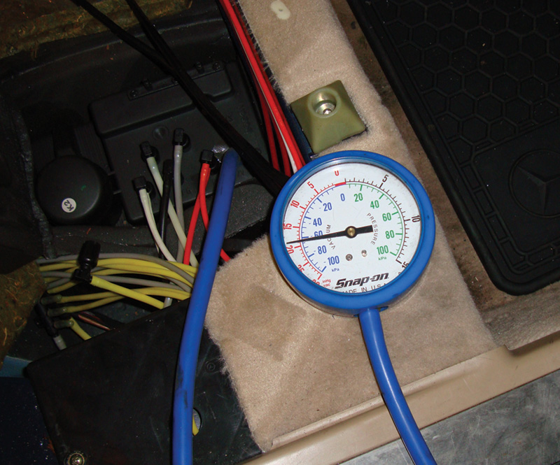
The PSE module contains its own
vacuum/pressure pump. Vacuum is used to lock the door. You can monitor the vacuum supply with a gauge while
commanding the system to lock. A good pump and pull almost 20 in. Hg.
You could use a hand-held pump to see if you can build and maintain vacuum. Depending on the number of lines and actuators, this could take quite a few strokes. Another way of testing for leaks is one that you have used for testing intake manifolds and EVAP systems: the smoke machine. It is invaluable tool for pressurizing the pneumatic system with smoke and watching for where it leaks out. Remember that there are check valves in the system and the pressure from your smoke machine may cause these valves to shut. Try keeping the pressure low.
Rounding Up
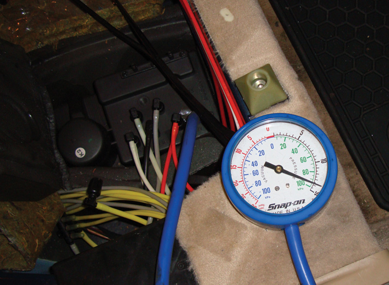
The same line that supplies vacuum to the individual door lock actuators also supplies pressure. A good pump can
produce almost 1.0 bar (14 psi). Of course, an air leak will decrease both vacuum and pressure.
Although the PSE module is now integrated with multiple control units, the basic function of supplying vacuum and pressure can still be isolated and tested. Remember that there are exceptions to the rules. For instance, the 230 chassis has electro-mechanical door unlock solenoids that react faster than pneumatically controlled actuators. This is a requirement for the “Keyless Go†system since just touching a door handle will command the door to unlock.
All that is required to diagnose the pneumatic system properly is vacuum/pressure testing the lines for leaks, monitoring scan data through SDS for door, trunk and lock position, and backing up these steps with actual testing of the wiring at the PSE module. Isolating the PSE system makes the diagnosis and testing easier and allows you to provide your customers with the safety and security they deserve.


0 Comments