 When customers comes in with a problem, for the most part they want it fixed at an affordable price. They don’t understand that there are about 20 major manufacturers and hundreds of different models and year changes. It’s your job to figure that out. So, when an automaker does something a little different, you’d better do your homework and understand this variation on the system you’re working on. In this case, Nissan Altima automatics with harsh shifting.
Where do we start? At the beginning?
In the old days, we used to farm out automatic transmission jobs to specialist shops. Most general repair facilities don’t have enough knowledge, experience or volume to make learning automatic transmission repair profitable. You might drive the vehicle just to make sure it’s not something else, but that’s about it. Now that there are electronic controls in transmissions, you may attempt to isolate the cause of the problem and see if it’s mechanical or electronic/electrical before you decide to send it out. If it’s an electronic/electrical problem, you may want to handle it in-house. We’ve learned from ignition and fuel injection systems how to diagnose these types of problems, right?
Well, this vehicle came in with hard shifting, or banging into gear (as much as a four cylinder can do that). After a road test to confirm that it was indeed a transmission problem, some typical checks were performed. We took a look at the fluid and determined that there was a lot of clutch material in it. This can make valve body pistons and electrical solenoids stick, which could be the cause of harsh shifting. A discussion was had with the customer and an agreement was made to rebuild the transmission. It made sense. A fluid flush could have been performed, but that might have helped the shifting situation only temporarily. The clutches would continue to wear. Now was the time.
After the rebuild was complete, the fluid was topped off and the car was road-tested. It went through all four of its gears, and went into lockup, but the shifting was still harsh, banging into each gear. This was what the shop had to face. While the repair was sold to properly repair a worn transmission, the customer’s view would naturally be that the symptom wasn’t eliminated, and that’s the kind of thing that will give a shop a bad name.
Time for a more careful diagnosis
The shop decided to repair the vehicle properly — no, completely. To start the diagnostic process, we needed to know what factors are involved in shift quality. Of course, there is the mechanical function of the transmission. However, it was just rebuilt, and since the rebuilder was qualified and experienced, we thought maybe we should start looking at the electronic/electrical control functions instead. Most transmissions have input shaft and output shaft speed sensors. The programming can use engine rpm and vehicle speed sensor signals to check shift points. Also, there are the actual solenoids that perform the shifts. Finally, there’s a solenoid that controls the operating fluid pressure.
Diagnosis of this kind of shift problem should start with a look at the car’s wiring diagram. Here, we saw what Nissan refers to as the Line Pressure Solenoid. This is commanded on during shifts to reduce line pressure and the load on the clutch baskets while they’re disengaging and engaging, thus making the shifts smoother. If the solenoid loses power or ground, the vehicle will still shift, but it will shift hard. Some manufacturers use a pulse-width-modulated ground to control the solenoid. This allows line pressure to be reduced by gradually opening and closing the solenoid.
![]()
 This Altima has a slightly different strategy. In the diagram, we saw that one wire goes directly from the ECM to the solenoid, and a second wire leaves the TCM, passes through a dropping resistor and then continues on to the solenoid. The solenoid is grounded directly through the transmission case. In this particular case, the solenoids were not replaced, but were tested and passed. This particular solenoid may not have been mounted or grounded properly. A resistance test between the solenoid and the negative battery terminal would be a good start. A voltage drop test on the ground would be another good idea, but would require dropping the pan for access. While we like V-drop tests, in this case it would involve extra time, so we left it until later.
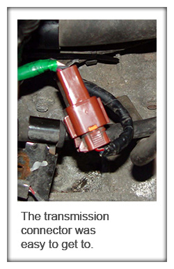
Getting back to the resistance test, we did it between the transmission connector, since it’s easy to get to, and the negative battery post. We’re not suggesting that you take the easy way out, but since the repair was already sold this additional diagnostic time was not being paid for. If resistance of the solenoid is about 3.0 ohms, you may be tempted to check current draw, but Ohm’s Law tells us to expect about 4.0 amps, and 3.0 to 3.5 amps is what you will see. If there’s more than that, the TCM will shut down operation of the line pressure solenoid and flag a code for it.
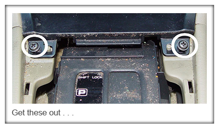
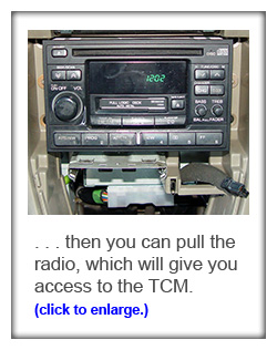
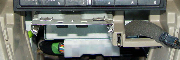
We still hadn’t looked at the wiring. If you want to check the whole line pressure solenoid circuit, you’ll have to access the Transmission Control Module. This way, you can check from the pin of the TCM to ground. Luckily, this is pretty easy. First, remove the shift lever cover. This exposes two screws that hold down the front cover. There are also two screws that are below the heater control panel. With these four screws removed, you can remove the front cover and expose the radio screws. Once the radio is out, you can see the two screws that hold down the TCM. After pulling out the TCM, you can check the entire circuit.
Here, we’re performing static tests — done while the system is not in operation. Measure resistance from either wire on the TCM to ground. If you see around 3.5 ohms on the wire directly to the solenoid and 15 ohms on the wire through the dropping resistor, those are good numbers, so you can move on. In this case, the readings were 3.8 and 20 ohms. Since the wire with the dropping resistor was a little high, we checked the resistor itself. It ohmed out at 20. How many times have you seen a component test fine, but still end up being the problem?
Bigger gun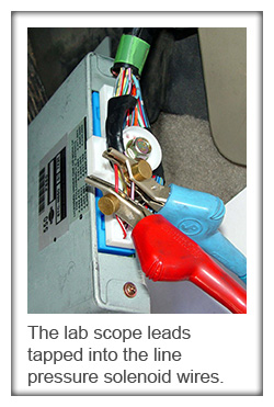
Remember, the solenoids were checked out of the transmission on a special tester, and they passed. Could the problem be in the computer? How do we find out if it is? It would be possible to monitor these two wires with a multi-meter, but you’d have to be able to watch the meter while the TCM is actually operating the solenoid. It makes more sense to watch this time-base signal in a time-base format. In other words, break out the big gun: your lab scope. This is ideal for monitoring the computer’s control of the solenoid while driving. Attach your scope leads to the two wires that control the line-pressure solenoid.
Something strange happened on this car. After checking the dropping resistor, the TCM set a Code P0745, which wasn’t present before. Now, at least we had something to hold onto and diagnose. Look at the scope pattern with the ignition switch turned on and right away you’ll see the TCM activate the line-pressure solenoid through the dropping resistor and the direct line. The TCM activates the solenoid three times when you turn the key on. This is the circuit test for the solenoid. If it fails the test, Code P0745 will be set.
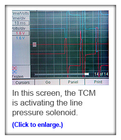 In the scope pattern, the pink/blue wire through the dropping resistor is the blue trace, and the red wire is the red trace. Advanced scope users will notice that the patterns go below ground. None the less, you can still see the line pressure solenoid being activated. Now, look at what happens when the dropping resistor is unplugged, tested with the DMM, and plugged back in. Notice the blue trace. This is new! By the way, this was when the TCM started flagging Code P0745.
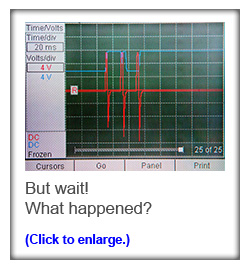
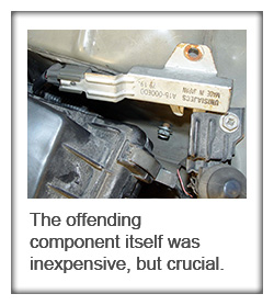
So, now we knew we had a circuit problem, and it showed up right after the dropping resistor got jostled. Just to cover all bases, we double-checked the line pressure solenoid from the transmission plug to the negative battery terminal and compared that reading to the resistance checks from the TCM to the negative terminal. They should be very close since only a few feet of wire would be added to the circuit. However, checking the resistance on the pink/blue wire with the dropping resistor reinstalled, we found an open circuit. We know the solenoid is not the problem because the resistance check on the direct wire is still 3.8 ohms. At this point, we assumed the dropping resistor had failed. The first time it was tested it indicated about 16 ohms (20 ohms overall circuit resistance minus the 3.8 ohms of the solenoid), but later it indicated open. The second scope pattern shows what happens when that circuit goes open.
Review
It would be easy to write articles on simple, straightforward diagnostic solutions, but we’ve all have had problems that were anything but straightforward, often resulting in many parts being replaced needlessly. This shop was thinking about pulling the transmission again and possibly changing the solenoids. Now that we know what was wrong, we realize that that would not have fixed the car. We now know to check the line pressure solenoid resistance and amp draw to determine if the solenoid is functioning. The transmission shop had the right equipment to test the solenoids properly, and that’s why they didn’t get replaced. We now know that the TCM pulses the solenoids three times at start-up and watches the voltage drop. If it doesn’t like what it sees, it will flag the code. In the beginning, the solenoid passed the ground resistance test, but after testing the dropping resistor, and probably bending or breaking the wire in the process, we saw the resistor fail. We learned to go over the electronic/electrical components of the transmission, and saved the headache of R&Ring the transmission and replacing the solenoids for no good reason. Now, with a new, relatively inexpensive resistor in the car, we can return it to the customer with confidence that the job was finally done right.
by Kerry Jonsson

0 Comments