
A happy customer is a comfortable one. You perform essential services to keep them rolling, but one indulgence they really enjoy is climate control. Here’s how to keep them as comfortable in their vehicles as they are in their homes.
Whether it’s a manual or automatic HVAC system, motorists just want it to work. Every time they get into their vehicles, either from the beach, or the air-conditioned shopping mall, the few minutes it takes to cool the cabin air feel like an eternity. Naturally, they are very appreciative of the service work you perform that keeps them comfortable. So, how can we keep their HVAC system functioning in a cost-effective and profitable manner?
Knowing how Volkswagen systems work, and familiarizing yourself with the various functions and options involved, can help save a tremendous amount of time while you are trying to figure out an issue a customer has brought you.
Volkswagen manual AC systems get their durability from their simplicity. Their similarities from year to year and model to model can make working on them a walk in the park in most instances, providing you are in the know. Electronically temperature-controlled HVAC systems are, of course, more complicated, but they have extensive self-diagnostic features to assist you. Here, we’ll look at how the basic manual AC system works, and what to look for when there are problems. We’ll also investigate the more sophisticated electronically-controlled systems, and what functions are useful for diagnosis.
Keeping Your Cool
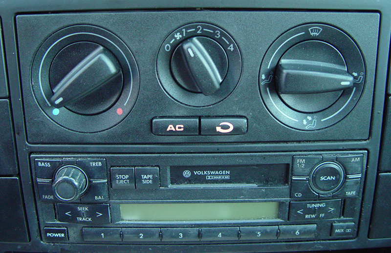
Since early 2000, Volkswagen vehicles have predominantly been sold with manual AC. Despite what you may think, modern manual AC systems don’t just rely on lever controls, vacuum switches, and cables. There’s plenty of wiring, too.
Manual AC systems are called that these days because there is no computer-controlled feedback to adjust cabin temperature. The passengers simply set a temperature and the system puts out what it can to achieve it. Some electrical inputs are used to protect compressor operation. There is an ambient temperature sensor, a refrigerant pressure sensor, and coolant temperature sensor to make sure conditions are right to turn it on.    Starting in the early 2000 model year, a cooling fan control unit monitors all these sensor inputs and manages the compressor clutch circuit as well as the cooling fans.
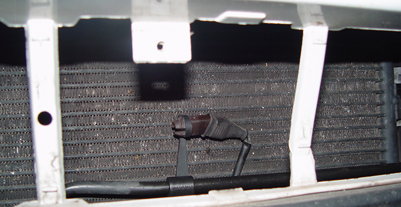
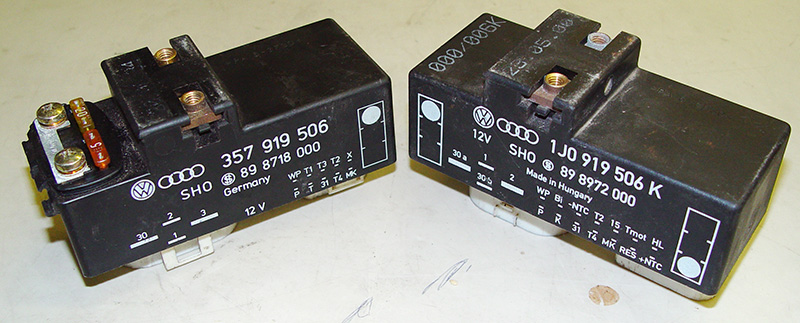
With a manual system, all of these inputs need to be working properly to activate the compressor. If any input were to fail, the compressor clutch circuit would open. Without a control unit with self-diagnostic capability, this means each input has to be checked using pin voltages. Whether you want to check the voltage signals at the cooling fan control unit, or each individual sensor, is up to you. The control unit is usually mounted on the driver’s side front frame rail. On a New Beetle, that would be under the battery tray, not all that easy to get to. Some cooling fan control units have strip-type fuses secured to the top, some do not, depending on the application.
Testing Input
Consider a 2002 Jetta VR6 with manual AC. Its coolant fan control unit has two connectors, one four-pin, and a larger 14-pin. On the four-pin
connector, you have the relay’s power supplies, a 6.0 millimeter solid Red in pin #1, and a 2.5millimeter R/Wtracer in pin #3. They should have battery voltage at all times. In pin #2 (a 2.5 millimeter R/W tracer) is the power supply out of the relay for low-speed fan operation. The final 6.0 millimeter R/W tracer is the power supply output for the high-speed fan.
The 14-pin connector is where the internal relays get activated, not only for the cooling fan, but also for the AC compressor clutch. Pin #6 is a Brown ground wire, and constant battery voltage comes in on pin #4, a R/Gr tracer. Power from the ignition switch comes in on in pin #9, usually a Bk/Bl tracer.
In order for the compressor to turn on, inputs are needed. The first check is on pin #8, a Bl/R tracer.    When the AC button is pressed and the blower is commanded on, you should see battery voltage.    Next, look at pin #2, a W wire. This is an unusual signal in that it is a five-volt square wave created by the refrigerant pressure sensor.    The duty cycle of the signal will change with the refrigerant charge. This is to indicate if the charge is too low or too high to turn on/off and damage the compressor.
Another signal that may inhibit compressor activation is that of the ambient temperature switch. Test for voltage between pins #5 (Bl/R) and #14 (Gn/Bl). If the signal indicates the air temperature is too low, it will not allow the compressor to run. Check these inputs to the cooling fan control unit whenever the compressor clutch won’t engage.
A Brief Description of Climate Control
The phrase “Automatic Climate Control” means that after setting the temperature in the cabin, an electronic unit monitors both outside and cabin temperature conditions and uses a programmed plan for how best to achieve and maintain the chosen setting. These settings vary from full defrost heat to MAX AC. Once a temperature is set, the control unit will automatically manipulate mode doors, temperature blend doors, and the recirculation door. There are manual overrides the passengers can select to control the mode doors’ position, cabin air recirculation, and AC compressor operation. Since the electronics are overseeing system operation, Volkswagen has implemented the same self-diagnostic features found in other on-board control units.   
You may not realize what your current scan tool is capable of. You may not even realize how much useful information you have at your fingertips.    You should hone your skills, reduce your diagnostic time and maybe get ahead of the “cost-effective diagnosis†game.
Volkswagen/Audi Automatic Climate Controlled Systems are endowed with similar self-diagnostic features to powertrain control systems. While the scan-based diagnostic features in the Auto-HVAC systems are extensive, the interface is proprietary, so without knowing what you are looking for it will be difficult to interpret the data being displayed. So how does this work?
For those of you familiar with VAG scan-based diagnostics, this will be a review. For those not familiar with it, welcome to the future. VAG is the factory proprietary scan tool for Volkswagen and Audi vehicles. If you purchase the European bundle for your aftermarket scan tool, you should be able to display this “factory†software, which allows you to communicate with all of the various control units in the vehicle. Each control unit is programmed to use the same software architecture, so what we’re about to describe will work on ABS, as well as SRS.
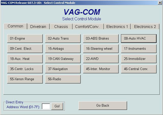
You can enter the self-diagnostic feature with your scan tool by simply picking the address word you need. So, what’s an address word? With the factory scan tool, a series of numbers is used to identify the various systems we can enter. These numbers are called “address words†in your technical literature.
Functions
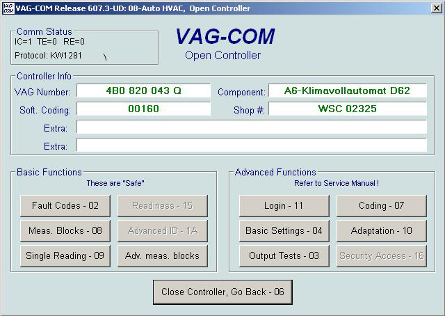
Each system has its own address word. On the Volkswagen/Audi factory tester, you need to know what address word represents each system.    Aftermarket diagnostic tools give the address word as well as a description of the system. In the case of automatic climate control, the address word is 08 (Auto – HVAC). Once you’ve selected the system, you will now be asked to select what function you would like to perform. You have numerous choices:
- Function 01 identifies the control unit.
- Function 2 is for pulling codes.
- Function 3 is for actuation mode.
- Function 4 provides ‘basic settings.â€
- Function 5 clears codes.
- Function 6 ends communication with the control unit.
- Function 7 allows you to code the control unit to the particular car it is in.
- Function 8 is for reading data.
There are a few other functions to choose from, but we are going to focus on the most important ones.
Starting with function 01, you will see that this merely identifies the control unit in the vehicle as well as its version coding. This information is useful if you feel the coding may have been changed in error, or a used control unit was installed and may not match the requirements of communicating with all of the other various control units in the vehicle. Each control unit is programmed to use the same software architecture, so what we’re about to describe will work on ABS as well as SRS.    You can enter the self-diagnostic feature with your scan tool by simply picking the address word.
Providing the control unit is the proper one, you can correct coding if necessary.    Function 02 is pretty self-explanatory. Auto-HVAC units are capable of self-diagnosis, and can identify faults in one or more components. These components are either sensor inputs, or actuator outputs. In the case of actuator outputs, you don’t always have to access the component and start our testing there. The other option is scan tool activation.
Function 03 is the mode in which you can take advantage of the scan tool and request that the HVAC control unit activate various outputs. You can listen for the activation, and/or perform electrical testing on the component being activated.
This allows you to verify that the control unit’s driver is capable of turning on any component in which you may suspect a fault.
Moving along to function 04, this is referred to as “Basic Settings.†In general, this provides a “reset†or ‘re-sync†of computer-controlled features.    The automatic climate control system needs to know the positions of the various temperature and mode doors in order to manipulate them if a change is requested by the occupant, or sensed by a temperature sensor. “Basic Settings” runs the control unit through the re-learn process, but more on this later.
Function 05 simply clears codes, and once you are done communicating with the HVAC control unit, you need to shut down this communication by selecting Function 06. This prevents corruption of software in the unit. Function 07 allows you to change the version coding, which is a way for you to tailor the control unit to the vehicle it is in. Vehicles come with more than one option. Each control unit must be made aware of these options in order to perform properly. This comes in especially handy when installing used parts.    Although the replacement control unit may have the same part number, the coding must be changed to accommodate the requirements of the vehicle being repaired.
Finally, Function 08 (sometimes referred to as data blocks, or measuring blocks) allows you to look at data, such as a temperature sensor reading, or actuator position. The tricky part is that these data blocks are also identified with numbers and are displayed in blocks of four. You must look up in a table what the data blocks indicate for each display group.
Reset
Once you have pulled codes, diagnosed a problem, and done a repair, you may need to reset the climate control system, especially if a mode door motor was replaced. This can be achieved through the “Basic Settings†feature. You will be prompted to enter a three-digit code. Leave the code “000” in the display and enter this mode. The positions of the doors are recorded, and they will then cycle to their respective end stops. Now, the control unit knows what the maximum and minimum positions are for each mode/blend door. When it needs to make a temperature adjustment as a result of changing conditions, it can make the correct change. Without knowing the proper position of the doors, it will make the wrong adjustment and output the wrong temperature.
Knowing the system helps cut down on wasted diagnostic time, and can make you money on all but the most difficult problems. You will end up with fewer comebacks, less stress, and a cool, happy customer.
Download PDF


0 Comments