 I first heard of Mercedes-Benz’s unique means of providing central locking back in the early ’80s. I was consulting for Broad Run Enterprises, an outfit that was engaged in putting service manuals on microfiche and providing a well-organized index. While that may seem laughably primitive now, it was actually a pretty good system.
Regardless, one of the other tech guys there asked me why vacuum lines ran to the doors of the Mercedes he was researching. Well, I’d worked on all kinds of cars by that time, but had never run into this. So, I investigated and discovered another whole approach to what every other car maker did electrically, and a unique system to learn about.
Instead of using solenoids to snap those locks, the M-B engineers decided it was better to do the job pneumatically — more force, no unpleasant noise, great durability. That, however, presents us in the independent auto repair business with a new set of diagnostic issues, and if we’re going to be one-stop car-care centers for our patrons who own Mercedes-Benz vehicles, we need to understand how it works and how to diagnose and fix it.
Since about 1986, most M-B cars have had what’s called “multi-point” central locking. If you’re not sure what you’re dealing with, go to the passenger’s door and unlock. If all the other doors do the same, you’ve got multi-point. If not, either you’re working on a car with the older single-point system (which unlocks only from the driver’s door), or there’s a problem. But since you’ve been presented with a complaint about this feature, you may be unable to get any action out of it whatsoever. That means you’ve got to dig deeper.
What’s involved
You need to understand the components and operation of a typical system before you can proceed (reading the owner’s manual will give you an idea of how it’s supposed to work from the customer’s point of view). First, there’s the pump, which supplies both the vacuum (for locking) and pressure (for unlocking) upon which the system depends. This may be located in the spare tire well, under the back seat, or perhaps in the engine compartment on older models. If it’s not in the engine compartment, it’ll be encapsulated in foam. It has two electrical connectors, one round and the other flat.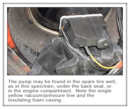
The pump should produce .5 Bar (7 psi) within two or three seconds. Pressure in the system is relieved 15 to 20 seconds after the pump stops. If there’s a heavy leak, the electronics that control it switch it off in 25 to 60 seconds. From about 1983 onward, the change from vacuum to pressure is accomplished by electrically reversing the rotation of the motor — negative control voltage for vacuum, positive for pressure. Previously, this had been done by means of a switching valve, but you’d have to be restoring classics for this to have any significance.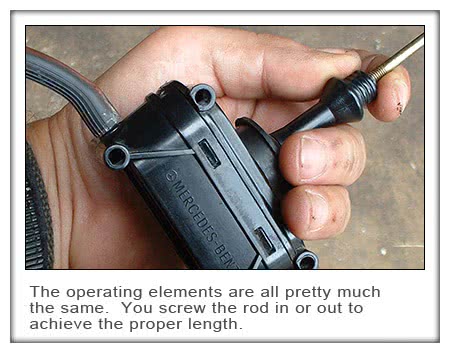
Next, actuation units (which M-B calls “operating elements”) are present at all the doors, the trunk lid and the gas cap flap. These are simple diaphragm-type pneumatic devices with linkage rods. All are very similar, but the ones for the doors are all black, while those for the trunk and filler flap are painted different colors on their upper portions. One yellow plastic line connects them to the pump.
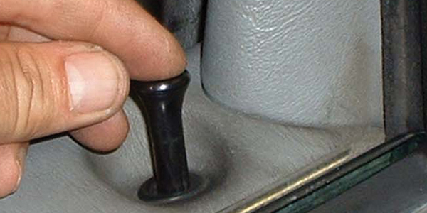
There’s an electrical switch in the driver’s door that controls the action of the pump, and one of the functions of the ignition switch is to assure that the doors can’t be locked while the key is in place. In the multi-point system, the passenger’s door and trunk elements also have switches.
The interaction between central locking and the alarm system is quite complex and would fit better into an article on the latter. All I’ll say here is that if the vehicle has an EDW Alarm system, you can disconnect the intermediate plug of the EDW cable harness from the connector (M14/1×2, or M14/2×2) and connect the central locking cable harness directly to the supply pump. If central locking works okay now, it’s time to delve into the EDW.
Diaphragm or line?
There are three types of possible problems: Pneumatic, mechanical, and electrical. Where the first is concerned, the most probable malfunction is, you guessed it, a leak, which is probably in the diaphragm of an operating element, or at a line connection. Those plastic lines themselves are pretty tough, but still a possibility.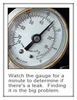
To find out whether or not a leak is indeed present, disconnect a line and use a manual vacuum pump to draw a vacuum and see if it holds. At 300 mbars (9 in. Hg), you should see less than a 30 mbar drop in the gauge in one minute.
But vacuum doesn’t necessarily tell the whole story. Sometimes a circuit that holds vacuum won’t hold pressure. So, pump it up to 600 mbars (9 psi) and make sure it doesn’t lose more than 30 mbars in a minute.
Okay, suppose there’s leakage. How do you find out where it is exactly? The logical first step is a visual exam of all the lines and connections you can see. If nothing’s obvious so far, start disconnecting lines at the pump and doing your vacuum/pressure tests, and work your way toward the doors, trunk and gas cap flap. Nobody wants to remove a door panel unnecessarily, but you may need to do so. Plug the element end of the line. If vacuum and pressure hold now, the diaphragm in the operating element is the culprit. Connect your test pump to it directly to make absolutely sure.
Mechanical problems come down to maladjustment of the length of the rods, perhaps due to a faulty previous repair, and to binding. In the former case, follow the factory recommendations for rod length. In the latter, bend the rod and lubricate the joints according to common sense. Remember to re-adjust the rod length when you’ve got everything moving unhindered.
Does the pump run?
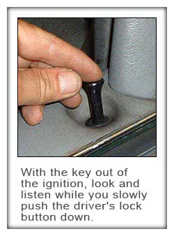
If you suspect an electrical glitch, the first thing to do is to listen for the pump to run (come to think of it, using your sense of hearing will help you locate the pump in the first place in cases where you’re not sure where to look). With the key out of the ignition switch, slowly press the driver’s door lock and you should hear the pump. No? Then examine the fuse (typically #15, but check the fuse box chart).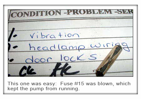
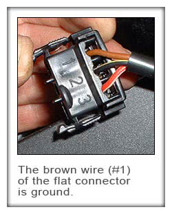 If that’s okay, unplug the pump’s flat connector (M14/1×1), remove the connector housing, push the terminals back on the pump pins and check for voltage between the terminals (the brown wire is ground) while you lock and unlock the system. If you don’t get at least 10V, go to the wiring diagram to track down the impediment to electron flow. If you’ve found sufficient voltage, but the pump still doesn’t run, it’s probably worn out. By the way, pumps with a black cover are not interchangeable with those that have a white cover.
If M14/x1 has a third pin, the car is probably equipped with orthopedic seats. The third pin is Circuit 15 to control that function.
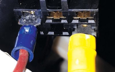
Finally, the round connector carries the switch signals from the three controlling elements (front doors and trunk) to the pump. Look for a change from ground to 12V as you move the actuator from unlocked to locked for each of the three pins.
by Bob Freudenberger

0 Comments