Catalytic converter diagnosis is easy! If you find a trouble code P020 or P0430, replace the converter and the car is fixed. Right?
Unfortunately, too many technicians believe the statement above is true. To them, it may even seem they have had a pretty good success rate replacing the converter every time they find a converter efficiency code.
After they replace the converter, the converter monitor passes and the Malfunction Indicator Lamp (MIL) goes out. However, unless all of the other possible causes for a converter monitor failure have been eliminated, a new converter may be just temporarily masking the root cause of the problem. In other words, they may have just sold an unnecessary converter replacement, or worse yet, failed to correct a problem that will cause the new converter to fail long before it should. Technicians who care about their customers and their own reputation will want to investigate converter efficiency codes fully, not just replace parts.
Myths and old mechanics’ tales
These are some of the things you may have heard other technicians say:
“OEMs make low quality converters to save money. They don’t make them like they used to. Catalysts used to last 20 years before they had a problem, now they fail after only five years.â€
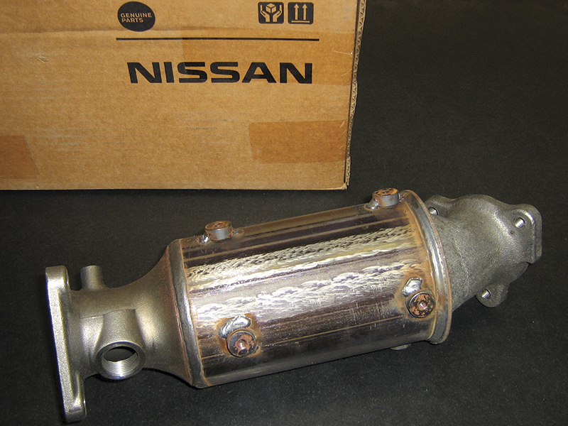
These are all false. Today’s converters are better than ever before, and the original equipment converter is the best converter for the car. If the converter does fail, a Genuine Nissan or Infiniti replacement is the best choice for your customer’s vehicle.
There are a couple of reasons your shop may be replacing more converters now than in the past:
- OBD II self-testing of the catalyst
- Less tolerance for degradation
Pre-OBD II converters were not monitored, so there were usually no signs of failure until the car failed the tailpipe portion of an emissions test. The criteria for failure of the tailpipe portion of an emissions test is more lax than the criteria to illuminate the MIL. Therefore, a converter that is bad enough to fail the converter efficiency monitor may easily reduce the emissions enough to pass a tailpipe test for many
more years.
Newer cars have tougher emission reduction goals. All emission reduction systems, including the converter, must do more than in years past. The MIL is designed to illuminate when the vehicle’s emissions are estimated to exceed 150% of the Federal Test Procedure (FTP). The FTP is a series of emissions tests performed on new models before they are certified for sale in the US. As the FTP requirements become tougher, the threshold for minimum converter efficiency also becomes tougher.
In summary, today’s converters are not lower quality, quite the opposite is true. They are simply held to a much higher standard than in the past.
“There’s no need to bother with ECM calibrations. It won’t help. Just replace the converter or the car will come back.â€
Checking for TSBs and ECM updates should always be the next step when you find a converter efficiency code. There is no guarantee an applicable re-flash will be the solution for every situation. But, even if does not correct the problem, and the converter still needs to be replaced, the calibration update will add service life to the replacement converter.
Old school converter testing – don’t bother
Older techs may remember a number of convertern testing methods including:
- invasive testing
- temperature testing
- various cranking tests with a warmed converter
- HC testing while disabling spark on one cylinder
- NOx testing under preset engine operation criteria
Two things all of these methods have in common is that they are completely unnecessary and potentially misleading when working on OBD II cars. When working on an OBD II car, the goal is to satisfy the ECM so it will turn the MIL off. The ECM is monitoring the O2 sensors to make its decisions, so you should be too – either directly or indirectly.
Working without a Consult III
Graphing the front and rear O2 sensors is a test that can still be used if you don’t have access to a Consult III. However, you may find that the results of this test are a little too inconsistent to be used with confidence, especially considering the cost of today’s catalysts.
If you do use this test, don’t wing it, use the manual. If you find the rear O2 sensor mirrors the front when the converter has reached operating temperature, the converter is surely bad. However, modern Nissans will set a code long before the sensor one and sensor two patterns start to look the same. Follow the procedure in the service manual exactly: warm up properly, count the cycles precisely, and use the switching ratio specification from the manual. On vehicles that use a front AF sensor instead of an O2 sensor, Nissan provides a rear O2 sensor frequency specification instead of a switching ratio specification.
Another test that can be used for catalyst diagnosis without access to a Consult III is the catalyst efficiency monitor. A “monitor†is the self-test performed by the ECM. Its failure is what caused the MIL in the first place. The check engine light and converter efficiency code tell you the monitor failed. The Mode 6 data will tell you “how badly†the test failed.
You can access Mode 6 test results with a generic scan tool. Once this information is noted, you can clear codes and run the monitor again by performing the prescribed drive cycle. After the monitor is complete, you can read the Mode 6 results again and compare. Mode 6 results can be used to:
- confirm a problem is still occurring
- find a marginal, but still passing, monitor
- confirm the efficacy of a repair
A complete discussion of Mode 6 is beyond the scope of this article, but you can find additional information in the service manual, including monitor information and drive cycle procedures. Just look in the On Board Diagnostic System section of the Engine Control System chapter.
Diagnosis with the Consult III
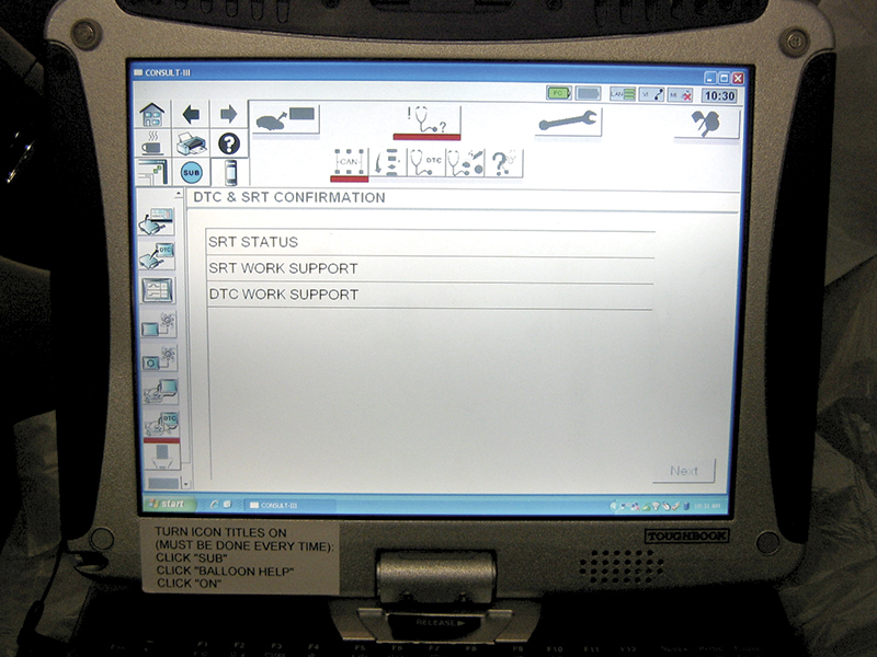
It will probably come as no surprise that diagnosis is a lot easier when you have the right equipment. The Consult III provides a feature called DTC/SRT confirmation. The DTC (Diagnostic Trouble Code) and SRT (System Readiness Test) confirmation procedure will run a specified monitor with a menu-driven test. A simple five-minute test and you’ll have your answer – either yes, the converter monitor is still failing; or no, the converter monitor is passing now.
Causes of converter efficiency codes
It’s not enough to verify poor catalyst function by checking the O2 sensor switching ratio, Mode 6 data, or using Consult III DTC/SRT confirmation. There are a number of problems that can cause a good converter to perform poorly. Once poor function is confirmed, the next step is to eliminate any other potential cause. This is the essence of modern converter diagnosis.
Misfire
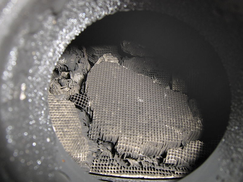
An engine misfire can permanently damage a catalyst. If the old converter element is broken apart or melted, a misfire is the most likely cause. This will need to be corrected before the car is returned to the customer. Converter damage caused by misfire will not be covered by warranty.
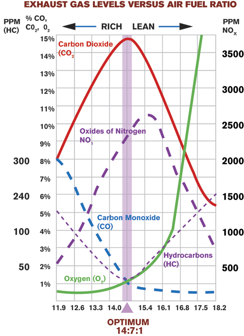
A misfire will also reduce the converter’s efficiency. When a misfire occurs, the air/fuel charge will pass unconsumed into the exhaust. The increase in exhaust oxygen content will affect the oxygen sensor and skew the air/fuel mixture, leading to a rich mixture. A mixture other than stoichiometric (14.7:1; also called Lambda) will decrease the catalyst’s efficiency. Extra oxygen in the exhaust will also adversely affect the converter’s ability to reduce NOx.
Timing
Incorrect ignition timing is not common on modern cars as most do not have adjustable timing. However, incorrect ignition timing will affect converter efficiency, so it shouldn’t be overlooked.
Pre-cat exhaust leaks
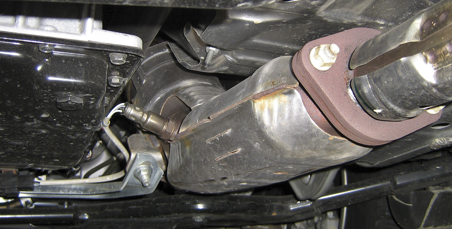
A pre-cat exhaust leak can have a great effect on a converter’s operation. Three-way converters require the absence of oxygen to break the NOx into O2 and N2. The oxygen generated in this reaction (referred to as reduction) is used to fuel the oxidation reaction, where CO and O2 are converted to CO2, and HC is converted to H2O and CO2. If there is an air leak in the exhaust before the converter, the converter can’t work properly.
It doesn’t take a big exhaust leak to cause a problem. In fact, you may not even be able to hear the leak with the engine running in the bay. Try the following to find smaller leaks; wet a couple of shop rags and have an assistant hold them over the tail pipe with the engine running. This will increase the exhaust backpressure and make small leaks more audible. A mechanic’s stethoscope with the tip removed can be handy for checking for leaks hidden under heat shields.
Improper air fuel ratio
Air fuel ratio will have a huge effect on how well a catalyst performs. A mixture of 14:1 will decrease oxidation efficiency about 70%. A mixture of 15:1 will decrease reduction efficiency about 70%. In other words, an “A+†converter can drop to an “F-†with a mere 3% change in mixture.
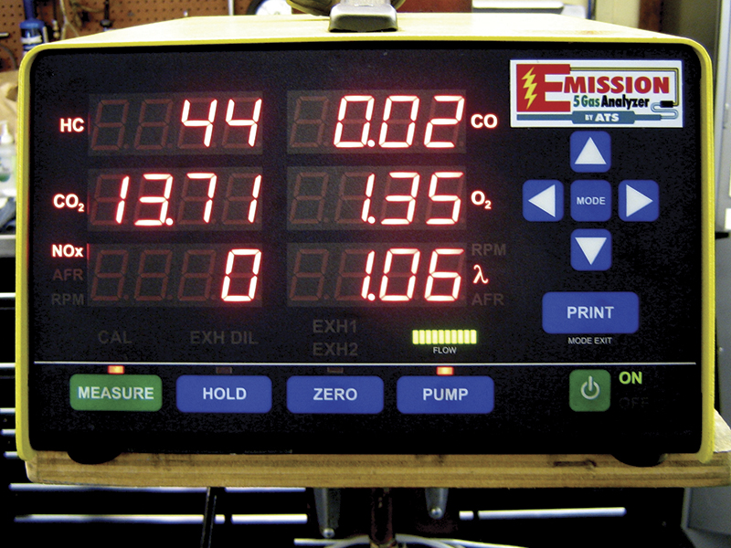
Average air fuel ratio can be measured with a five gas analyzer. Some analyzers display air fuel mixture expressed as Lambda. Lambda is convenient because deviations from the ideal ratio are expressed as a percentage. For example:
- Lambda 1.0 = 14.7:1
- Lambda 1.1 = 10% too lean, or 16.17:1
- Lambda 0.95 = 5% too rich, or 13.97:1
To calculate Lambda from an air fuel ratio measurement, use the following formula:
MEASURED AIR FUEL RATIO ÷ 14.7:1 = LAMBDA
To calculate air/fuel ratio from Lambda, just reverse the formula:
LAMBDA × 14.7:1 = AIR FUEL RATIO
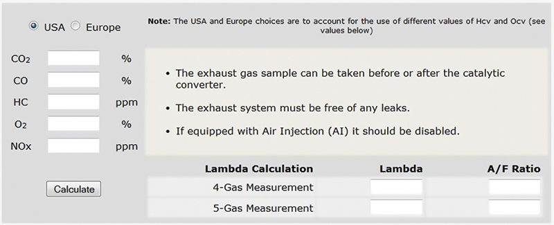
If your analyzer does not have a Lambda display, you can use a Lambda calculator to verify accurate fuel control. When HC, CO, CO2, O2, & NOx readings are entered into the calculator, a Lambda value will be displayed. A variety of Lambda calculators are available online.
When investigating a converter efficiency code, it’s important to check the air fuel mixture under the same conditions required to run the converter monitor. The converter monitor does not run while the car is idling in the bay, so measuring mixture at idle may not be helpful in determining whether mixture was a factor in causing the code. Freeze frame data is very useful to find and duplicate these conditions.
It may not be possible or convenient to bring your five gas analyzer on a road test with you to duplicate the conditions found in the freeze frame data. Once the O2 or AF sensors’ accuracy has been verified with the five gas, a scanner is a better traveling companion, since it is very portable and easy to set up.
Another advantage to driving with the scan tool is that you’ll be able to monitor fuel trim, also called AF ALPHA on the Consult III. Total fuel trim is the amount of correction applied to the base fuel schedule. Excessive deviations in fuel trim are an indicator of a problem.
For example, excessive negative fuel trim might be caused by a leaking injector on one cylinder. A leaking injector would cause one cylinder to run very rich and the others on the same bank to run very lean. This would not be good for converter efficiency!
Excessive positive fuel trim might be caused by a leaking intake manifold gasket on one runner or a clogged injector. This would cause one cylinder to run lean and the others on the same bank to run rich. This too, would not be good for converter efficiency.
Looking beyond average mixture
Mixture swings occur because of delays in A/F ratio correction. The lower the amplitude of the swings, the more efficient the converter will be. When a converter efficiency code is found, checking average mixture is important, but so is checking the swings.
Large swings in STFT are one indicator of slow correction. However, normal swing will vary from car to car. If you are familiar with normal STFT swings on the model you are repairing, or you have a known-good vehicle for comparison, you may find STFT a convenient quick test, but not a definitive one. A better method is to check the O2 or AF sensor directly.
Checking the O2 sensor
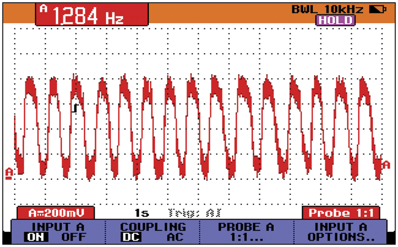
An oxygen sensor’s condition can be gauged by checking its output with an oscilloscope. The key components of the signal are:
- cycles per second, or Hz
- maximum voltage
- minimum voltage
- rise time with sudden enrichment
The first three measurements should be taken with a fully warmed engine running at 2,000 rpm. The O2 sensor frequency (Hz) should be measured over a 10 second period, as it is a very slow signal, so your oscilloscope should be set to 1 sec/div. The minimum requirement is usually five complete cycles in 10 seconds (or 0.5 Hz), but a good O2 sensor will produce 10 or more cycles per 10 seconds (or ≥ 1.0 Hz). This gray area between “minimumâ€, where a P0130 code will set, and “goodâ€, where the converter will be happy, is the reason for checking the O2 sensor directly instead of relying on a code to set.
The oxygen sensor voltage must rise above 0.6 volts and drop below 0.3V to avoid setting a P0130 code. Once again, a good sensor should perform much better than that to keep the converter happy. If the sensor is good, the maximum voltage should exceed 850 mV (0.85V) and minimum voltage should drop below 150 mV (0.15V).
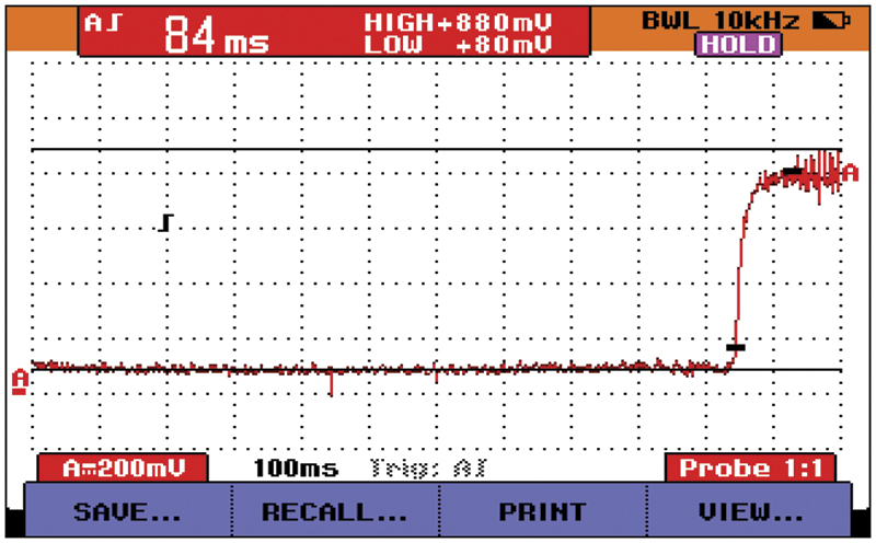
Finally, rise time should be measured. The scope should be set to 100 ms/div for this test. The time the voltage trace takes to rise from low (< 150 mV) to high (> 850 mV) should be 150 ms or less when the throttle is snapped.
Checking the AF sensor
An AF sensor’s output is best checked with a scan tool. If you have a Consult III, you can run a DTC confirmation for the B1 AF sensor to verify it’s in good condition. If not, you can monitor the AF sensor PID in the data list, paying particular attention to the amplitude of the output, and comparing against an identical known- good vehicle. As the AF sensor deteriorates, its response to throttle snaps will decrease. When working with non-CAN vehicles, you’ll need to create a custom data list with only the AF sensor; otherwise the slow data rate can skew the results.
Make the right decision
A converter efficiency code may very well be caused by a bad converter. The more modern the car, the more likely the ECM made the right call. However, you shouldn’t blindly believe everything the ECM tells you without doing your own testing. If you use the following checklist as your guide, you can be sure you are making an accurate diagnosis:
- Check for TSBs and calibration updates
- Verify the failure.
- Check for misfires.
- Check for exhaust leaks.
- Check for mixture control.
- Replace converter, as needed.




0 Comments