
In 1996, Volkswagen introduced an electronic throttle on the AAA V6. Integrating this with traction control, cruise control, and idle speed control makes for a safer vehicle. Keeping the system working properly is our job.
Believe it or not, fly-by-wire systems have been used on passenger vehicles for almost 20 years. For the driver, there’s no change in the way the car feels. The benefits are at an engineering level. An idle speed motor is no longer needed. All the electronic engine management system has to do is open and close the throttle plate to adjust engine rpm. Without mechanical throttle linkage, cable-operated cruise control can’t be used. That’s okay, though, because the Powertrain Control Module (PCM) just has to command the throttle plate to maintain the desired speed.
With traction control, it gets more interesting. Let’s say the amount the throttle is opened suddenly causes the wheels to start spinning. The driver could possibly go into a skid, or spin. With the traction control, computer and the PCM working together, the throttle can be automatically closed until traction is regained. Also, no longer do we have to worry about sticking or broken throttle cables. The benefits clearly outweigh the additional complexity of the system. But what do we do when something goes wrong?
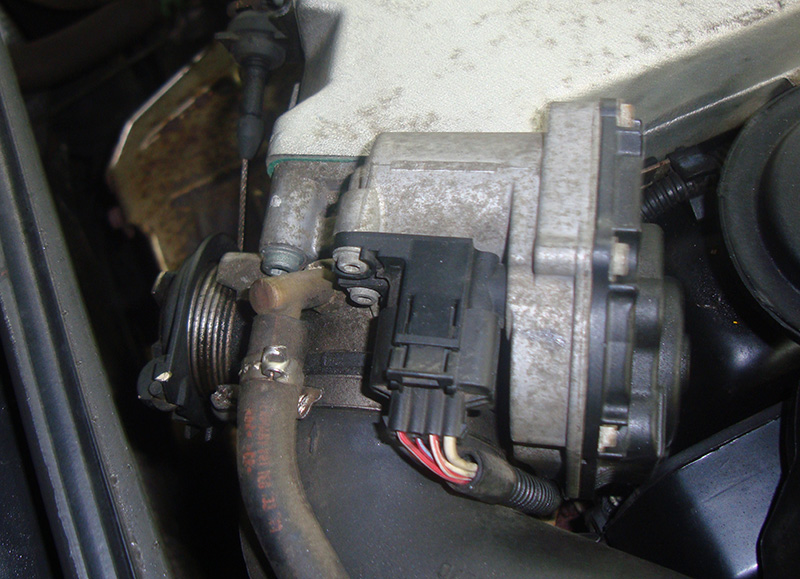
If you want to diagnose something, it helps if you know how it’s supposed to work. Volkswagen has used a few variations of electronic throttle over the years, so it’s best to be familiar with the changes. Earlier models use an electronic throttle module, but it still have a throttle cable for the ME5.X system. The cable mechanically opens and closes the throttle for typical city and highway driving. The electric motor in the throttle assembly only controls low rpm and idle situations. There is a Throttle Position Sensor (TPS) attached to the cable, which relays throttle requests from the driver. A second TPS indicates the position of the throttle motor. This is how adjustments are made to better control idle-speed situations. The two voltages are monitored by the computer and compared. If the control unit does not like one of the signal voltages, it can stop throttle control and flag a code.
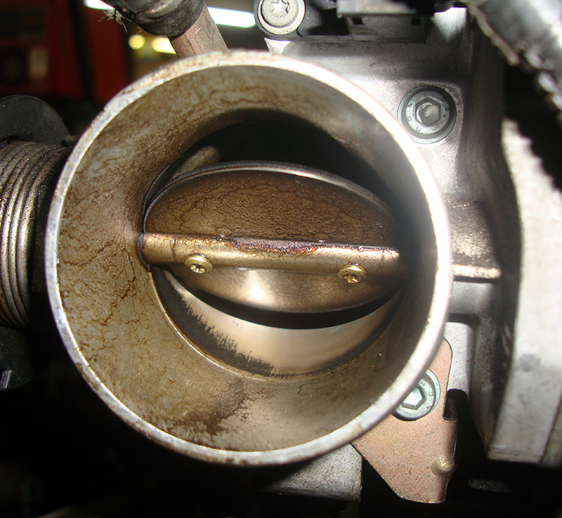
Over time, the throttle plates can cake up with carbon. This reduces the idle speed of the engine. The PCM can see this rpm drop and command the throttle plate to open slightly more until the proper idle speed is reached. There are limits for this compensation, however. If the PCM has to add too much air, it will flag a code and turn on the Malfunction Indicator Lamp (MIL, aka CEL for Check Engine Light). At this point, you need to clean the throttle plates and restore a normal idle. It’s important that you do this right:    Never spray cleaning solution into the throttle bore. With all the different carbon cleaners on the market, there is no safe way to predict if what you’re using will damage the internal components unless you purchase a Volkswagen recommended throttle body cleaner from your local dealer. Then, spray the solution on a clean rag and wipe any carbon build-up out of the bore and off the plates. This will help prevent any cleaning solution from making its way into the electronics.
If the problem is severe enough, you may have to perform a throttle adaptation. This may also have to be done if the battery has gone flat or been disconnected. You can do this with a VAG 5052 from the “Basic Settings†menu. Look for the proper three-digit code under repair information at www.erwin.vw.com. The numbers are typically 060 or 098, depending on year and model. What this procedure does is align the throttle assembly with the PCM. Typically, this has to be performed if you get    Diagnostic Trouble Code (DTC) P1580, or P1582. Just clearing the code may not keep the light off. During the adaptation, you will notice one of the TPS signal voltages change, and in field #4 you should see the message “Adapt OK†when it is completed. If the adaptation fails, the first thing you should check is battery voltage. It must be above 12V to perform the adaptation. If it is, you may have a problem in the throttle module.
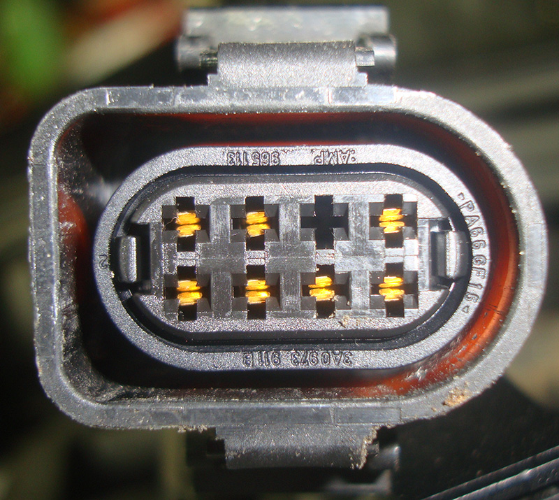
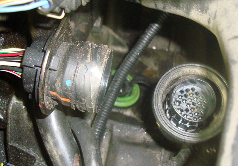
To test the throttle module, you can start with a quick scan of the voltages using your VAG. You can select “Read Measuring Value†block 060, or 098 to see the position sensors. They may be displayed in either voltages or throttle angles. Do not assume that the throttle body needs to be replaced if the readings are not correct. You should always support your diagnostic tests with actual voltage readings from a Digital Multi-Meter (DMM), or lab scope. Verify that the five-volt reference and ground are good, and check electrical connections. Fluctuating voltages from poor connections can lead to an incorrect diagnosis and a comeback. For instance, on the 1998 1.8L Turbo AEB engine you have an eight-pin connector for the throttle module. The pin layout is as follows:
- Throttle motor positive supply
- Throttle motor negative ground
- Idle switch
- Five-volt reference
- Position signal driver input
- Empty
- Sensor ground
- Position signal throttle motor
If the connector is unplugged, the throttle assembly defaults to a partially open position. The engine should rev to somewhere between 1,200 and 1,300 rpm, and, of course, codes will be flagged. With the control unit functioning normally, the idle speed should be about 900 rpm. You can monitor other measured value blocks to help determine what the problem may be. If you suspect a dirty throttle bore, search for idle adaptation values in your service information. This displays how much the PCM is opening the throttle to compensate for the low idle speed. If you have a vacuum leak, the computer may attempt to close the throttle to reduce the idle speed. This situation may also set additive lean system codes, so look for those as well.
Evolution
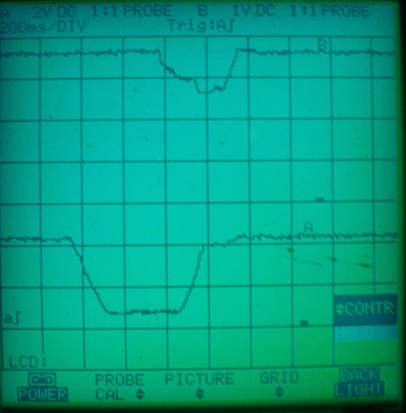
Volkswagen made a few changes on the ME 7.X systems, which make them true fly-by-wire. The cable has been eliminated, so the throttle plate is only opened by the motor. There are two throttle plate position sensors, which are opposites. With the plate closed, one sensor reads approximately .5 volt and the other should read about 4.5 volts. As the throttle plate is opened, the wire with .5 volt gradually increases toward 4.5 volts, and the wire with 4.5 volts decreases to roughly .5 volt. The PCM cross-checks these two voltages to verify “plausibility.†If the voltages do not make sense, the computer will go into fail-safe and no longer open the throttle plate.
If the PCM detects a binding throttle plate, it will also go into fail-safe mode and flag a DTC. There is an accelerator pedal position sensor mounted on the pedal assembly, which supplies input on the driver’s request. It also has two TPS signals    that provide signal voltages to the PCM. These increase as the throttle is opened, but at different rates. The #2 TPS signal is about half the voltage of signal #1 as the pedal is depressed. Once again, if the PCM does not like the signal voltages as it compares them, it will go into fail-safe. There are a few failure modes depending on what has failed. We’ll look at the different possibilities.
Imagine the Possibilities
If a failure has been picked up by the self-diagnostic portion of the PCM, it will enter one of three failure modes. These fail-safes are referred to as Emergency Running Modes 1, 2, and 3. Mode 1 occurs when one of the throttle position sensors fails, and you will only have about 60% power. The PCM uses the properly-working TPS and the    Mass Air Flow (MAF) sensor signals to cross-check one another while in this limited-power mode. A new addition is the Electronic Power Control (EPC) light in the dashboard. This lets the driver know that one of the emergency running modes is active. The MIL will also be activated.
If a fault has been found in the actual throttle motor, its power and ground supplies will be shut down. This is Emergency Mode 2. The throttle plate will default to its mechanical position of 1200 to 1300 rpm. Mode 3 is similar to Mode 2, but the PCM enters this mode when two TPS signals readings fail. You will not see any substitute values in the scan tool, so check the measuring blocks in the 06X range and you should see either throttle plate angle or signal voltages. If you want to scope the signal key-on/engine-off, you will not get the throttle open completely. The trick is to put the vehicle in gear, then apply the throttle. It should open completely, and you can test the full range of both TPS signals. There are no serviceable components either in the accelerator pedal position sensor or the throttle module. They both need to be replaced as an assembly.
In Conclusion
Understanding how the electronic throttle functions and how it works with the PCM will reduce your diagnostic time and lead to more accurate troubleshooting. Try to point out that billable services such as throttle bore cleaning and resetting throttle adaptation are required for the system to function properly. If the customer enters one of the emergency running modes, inform him or her that these fail-safes provide for a safer driving experience, and who wouldn’t want that?
Download PDF


0 Comments