by Phil Fournier
 We technicians learn best by doing, not by reading or listening, or even watching. This makes the automotive instructor’s or magazine article author’s job a difficult one. But sometimes I read an article or go to a class and come away with a new sense of confidence that I will be able to use the knowledge gained to good effect the next time I am faced with a diagnostic dilemma. I gained just this sense of confidence after attending a Standard Motor Products Network Diagnostic Strategies class. My goal in this article is to see if I can pass along some of that confidence to others trying to learn how to solve a problem of “No Communications,†“no bus.†or no-start/no-crank issues related to network problems.
 As you probably already know, networks have been with us for 20 years and are with us to stay. I won’t bore you with terminology and techno-speak related to networks beyond what is necessary for this article and the one vehicle repair I am going to cover. The vehicle in question was equipped with two networks, a single-wire and a two-wire. It would talk on one of the two networks, and that knowledge is key to doing the diagnosis. Almost all networks report to the DLC for diagnostic purposes and therefore a tool like the LineSpi by AESwave is very useful.
Our vehicle was a 2001 Dodge Durango with a collection of odd complaints, among which was a dash display that read “no bus†where it should have registered the mileage, dash gauges that usually didn’t work, and occasional ringing of the door chime or seat belt chime, even though the doors were closed and the seat belt fastened.
Naturally, I started my diagnosis with a scan tool. I had on loan a Snap-on Versus scan tool with the latest software, so I thought I would try it first. It auto-identified the vehicle without trouble, which is always an encouraging start. I could not find a function on the tool to scan all modules, so I began checking them one at a time.

I quickly found that I was able to look at all data and codes in the PCM and the TCM. I was unable to look at data in the ABS module, the Airbag module, and the Body module. But I began to wonder, “Where are the HVAC and MIC (Mechanical Instrument Cluster) modules on the Verus screen?” Since the dash indicated “no bus†and the PRNDL didn’t indicate the correct gear, I knew that the MIC was part of the network. I figured I’d better get more information before going forward. I needed to know why I could talk to two modules on the bus without a problem, but not to three others. I needed to know how many total modules were aboard this vehicle, and how they talk to each other. What “language†do they talk in? I went to my Alldata information system and after entering the vehicle information, I followed this thread: Powertrain Management, Computers and Control Systems, Information Bus. This is what I found:

So, this Durango has two information buses. One is an SCI bus and reports to the DLC on pins 6, 7, and 14. Pin 7 is a shared transmit wire for both the PCM and the TCM, while 6 and 14 are the receive wires for the PCM and TCM respectively. But since I could talk to both of these modules, I’m more interested in the other bus, the PCI bus that talks on Pin 2, a single-wire communication network. The other diagram does two things for me: It tells me how many modules may be on the bus (as many as 11), and it tells me that I have a Diagnostic Junction Port Connector. Having a central location where most or all of the single-wire bus signals intersect is a huge benefit — I have lucked out on this vehicle. (By the way, many GM vehicles use a similar device known as a splice pack.)
But the Versus was only showing me five modules; how many are actually present? Well, this Durango is a stripped model — two-wheel drive, and not equipped with an Immobilizer (SKIM), overhead console, or the upgraded radio, so I could eliminate those modules (the Central Timer Module is Chrysler’s name for the BCM). Still, the Versus has come up short; it will not look at two of the seven modules, and I really need to be able to talk (or attempt to talk) to all of them. I’m going to have to switch to my DRB3.
My DRB3, however, yields similar results; I can still only talk to the PCM and TCM and cannot talk to the other five modules on the PCI bus. I’m pretty sure it’s safe to assume at this point that the reason I can talk to the PCM and the TCM is because the scan tools are talking to them on the SCI bus, which is working fine. I cannot talk to a single module on the PCI bus, so something is causing a fault there.
It is at this point that I used to be totally lost. I did not know what to do next. But let’s think about it for a minute. What can go wrong with a communications network such that all communication is lost? The list is actually quite short:
- The bus can be shorted to ground
- The bus can be shorted to power
- One or more of the modules may be corrupting the signal on the bus
- Possibly one or more of the modules is lacking power or ground (generally this will drop out only the module with the problem, though, not the entire bus)
Ok, so what’s the next step? Well, using my LineSpi and my Pico scope, I took a look at the waveform on Pin 2 of the DLC, which is where my PCI bus reports to for the purposes of diagnosis. This is what I saw:

I eliminated possibilities 1 and 2 with a simple single test. The bus was not shorted, either to power or to ground. In fact, the waveform looks just fine. But I know it is not fine. How do I know that? Because neither scan tool understands the language that is being spoken. There was no communication. That is a simple but hard-to-grasp concept. We techs who are used to looking at scope patterns want to SEE something bad. But in this case, we cannot see a thing, yet we know it is bad because the tool that CAN see something there is the scan tool. And it was telling me, “I can’t understand a thing this bus is saying.â€
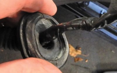
So, what do I do now? Well, remember that this vehicle has a Diagnostic Junction Port for the PCI bus. Chrysler techs have a tool that will adapt this plug right to the DRB3. I don’t have that adapter, but I have a method that works fine for me. Here (right) is a picture of the DJP:

Do you see that red thing stuck in the port? If I pull that out, all of those Violet/Yellow wires become separated from the bus. Once I’ve done that, I can use my trusty paper clip to connect them to the DLC pin 2 one at a time like this:

Once I’ve made that little jump, I can do two things: I can see if the scan tool will talk to that particular module, and I can look at the waveform to see if it looks any different. As you can see below, the waveform has not changed much (other than a shorter time base which spreads the waveform out and a minor difference in amplitude).

 Nevertheless, while I was looking at this waveform, I was also talking successfully (for the first time) to the HVAC module with the DRB3.
The procedure I followed is a bit tedious and time consuming, but it works. I went down the line one by one and looked at the modules on the PCI bus. I could talk to all of them except the MIC and the BCM (Central Timer Module). It bothered me that I can’t talk to two of them. I wasn’t particularly surprised that I couldn’t talk to the MIC. After all, it was kind of pointing at itself with the “no bus†message in the odometer, plus the non-working gauges and PRNDL. But I had tested most of the stuff done by the BCM and it all seemed to work. The RKE (remote keyless entry) fobs, the horn, the dome lamp, and the intermittent wipers all worked. I decided to recommend replacement of the MIC with a recheck of the CTM once that was done. This is a slightly dangerous strategy from a customer-relations standpoint and reflects my continued lack of complete confidence in my network diagnostic skills. But both components are relatively expensive and I felt I should err on the side of caution.
 After a couple of days of waiting, the MIC showed up, preprogrammed with the vehicle mileage. I plugged it in with some fear and trembling and used my paper clip in the DJP to check its operation first with nothing else on the bus. To my relief I get this message on the DRB3 (right):
Wow, what a relief! Next, I plugged the red connector back into the Diagnostic Junction Port and tried again. No joy! I cannot talk to anything with the CTM (BCM) connected to the bus. Ok, what are side-cutters for? I decide to try this:

It worked! With the CTM isolated out of the bus, I went down the line and talked to every module. As you can tell from the butt connector, I had tried this trick before to cut out the MIC and the CTM to see if I could connect all the rest and talk with the scan tool — I could. But could I get away with this kind of a “fix?†I looked again at the list of functions for the CTM.

I realized that I could offer the customer the option of leaving the CTM out of the bus since on this base vehicle it is not needed for it to start and run. If it had been a “Highline” model, without the bus the engine would not even start, and the steering wheel radio volume controls would not have worked. But in this configuration, the only thing that would be lost is the ability to do diagnosis on CTM-related functions effectively since we cannot talk to it. But everything else it is in charge of works fine without the module being able to talk on the bus.
So, the 2001 Durango was “fixed.†True, not completely fixed. The CTM would have to be replaced to bring everything back to life. But the dash was working and none of the funny stuff was happening with the chimes and warning lights. The customer was happy and I was happy to have been able to use information learned from the Network Diagnostic Strategies class to successfully deal with what would formerly have been a very scary diagnostic dilemma.
To summarize, what did I need to successfully diagnose this vehicle? I’ve split the list up into “Have to Have†and “Nice to Have.â€
Have to Have:
- A scan tool that can talk to every module on the affected bus
- An information system that will diagram bus operation and locate critical components like the Diagnostic Junction Port
- A meter to look at bus voltages
Nice to Have:
- A LineSpi DLC breakout box or equivalent to give easy access to waveforms while providing a scan tool interface
- A lab scope to look at bus-generated waveforms
- An adapter plug for the scan tool that would break into the bus via the Diagnostic Junction Port
As I stated before, I don’t have the adapter plug for the scan tool, the last item on the “Nice to Have†list. I imagine it would have saved me quite a lot of time. I would feel much less comfortable using a voltmeter as opposed to a lab scope doing this kind of work, but essentially a voltmeter would have provided much the same information in this particular case.
I’m not going to pretend this was a flat-rate diagnosis. I didn’t check how long I spent, but it was probably better than four hours, much of it due to my uncertainty. I will be faster next time, now that I have a level of confidence in what I was doing. I hope this article will give you some level of confidence as well.
0 Comments