In this article, we will cover a few different repairs that don’t take a lot of time, but knowing these situations can definitely help with repairing these vehicles.
Electric Trunk Repair
Here we have a customer with a 2010 S40, stating that the trunk will not operate correctly (will not open without going inside and pulling the release). This can be due to a few different things. Perhaps a trunk latch is to blame, or maybe the micro switch in the release mechanism is not working correctly. It could also be a harness problem.
First off, let’s connect the vehicle to VIDA and read the system to see if there are any current codes for this problem. If there are no codes for the rear tailgate, go to the symptom related diagnostic procedures in VIDA. Go to Electrical Systems, Other Electrical Equipment, number 36, scroll down to Checking Selector Switch In Tailgate and click on it. Here you will be able to check the function of the switch on the tailgate by clicking on the VCT 2000 symbol.
Press in the tailgate switch; it should be activated when the switch is pressed in. If not, remove the handle at the tailgate to check the connection.
There are four screws that hold the handle on; remove the screws and access the micro switch. With a test light, we can check for power and ground coming into the switch. If power and ground are present and the tailgate is still not opening correctly, its most likely the micro switch in the handle. Replace the handle.
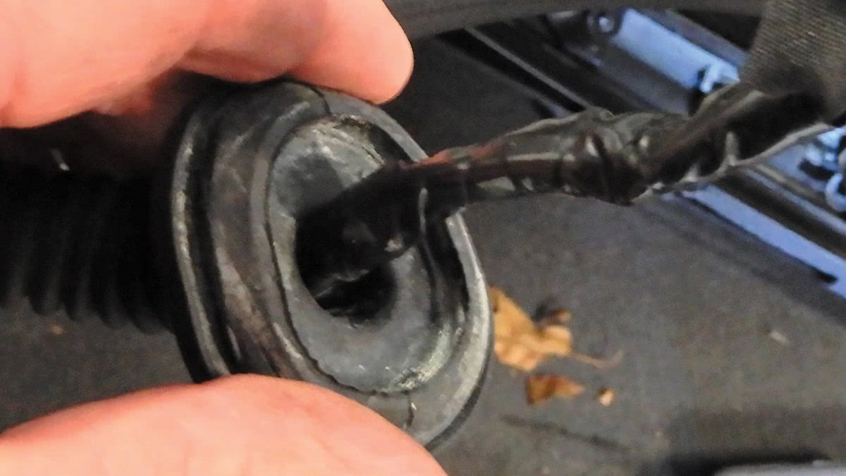
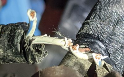
Many times on this model, the wire harness can wear out from repeated opening and closing the trunk lid, and the harness and the wires will become bare or even broken at times.
When replacing a harness of any sort, it’s a good idea to disconnect the battery to avoid any electrical issues with the vehicle. Always disconnect the negative side of the battery first. On some models, it’s a good idea to wait five minutes to let the modules in the vehicle go to sleep.
Remove the inner trim panel using a trim removal tool for the clips that hold it in place. This will expose the wire harness; now you can disconnect all the connectors at the lock mechanism, license plate lights, and so on. Disconnect all of the wire harness hold-down clips and tie downs that hold it in place.
Remove the wire harness from the trunk lid and where it connects inside the trunk. Install the new wire harness; insert the harness the same way it came out. Secure the grommets from the trunk to trunk lid, and connect all electrical connectors. Secure the clips and tie downs for the harness.
Once the wire harness is in place, connect the battery negative terminal and check the function of the trunk lid, making sure that it closes and opens correctly, and that the locking and unlocking functions work perfectly.
Reinstall the trunk trim panel, making sure that the clips and fasteners are secure in place.
On a 2014 S60, the trunk system operation is a little different. The system has a keyless entry system that is integrated into the central locking system. There is no locked mode on the trunk lid. The Central Electronic Module (CEM) will activate the trunk lid when the switch on the trunk lid has been pressed.
The trunk lid can also be opened inside the vehicle via the switch at the Light Switch Module (LSM). The remote key can also unlock and lock the doors and the trunk. There is a button on the remote that is dedicated to unlocking only the trunk.
Like the S40, when the system doesn’t work correctly, troubleshoot the problem depending on what doesn’t work. Check all the functions of opening the trunk lid. Try opening the trunk via remote control, the switch on the dash at headlight panel, and the button on the trunk handle.
If the trunk can be opened with the switch at the headlight panel and the remote control, but not at the button at the trunk handle, the problem is probably downstream. It is possible there is a break in the wire harness between the switch and the button on the trunk handle and the CEM.
Check the fuses for the trunk handle, making sure they are not burned out. Make sure that the glove compartment is not locked and in valet mode; this will also lock the trunk and you won’t be able to activate the unlock function from the trunk handle button.
You can check this function in VIDA under Vehicle Communication in the CEM under Private Locking.
To check the switch in the trunk handle in VIDA, go to Vehicle Communication CEM Parameters and read out the switch in the handle while pushing the switch. If nothing happens you will need to remove the inside panel at the trunk.
Measure the voltage drop at the switch—not activated and then activated. Battery voltage should be present when not activated, and activated should be close to 0 voltage. If the switch has battery voltage, the switch is supplied correctly. If the switch voltage is not close to 0 voltage when activating, then the switch is bad and will need to be replaced.
If voltage drop is not approximately battery voltage at the switch when the switch is not activated, but is continuously 0 volts, this indicates a fault. Either the switch is short circuited or the switch doesn’t have the correct power.
Disconnect the switch and check voltage drop at the harness. If the voltage drop between the wires in the harness is approximately the same as battery voltage, then the wire harness is OK and the switch has the right amount of voltage.
If you can measure the resistance of the switch, and if the switch closes the circuit continuously, the switch will need to be replaced in the trunk handle. If, when measuring the voltage drop in the harness to the switch is always 0 volts, there is a problem with the wire harness to the switch at the trunk handle.
To check the latch motor, go into VIDA, CEM Activation; if the trunk does not unlock, measure the voltage drop at the latch motor. If the voltage drop is battery voltage, it’s most likely a problem with the latch motor and it will need to be replaced. If the voltage drop is close to 0 volts, check the wire harness for a problem.
Replacing Gear Selector Lever Assembly with Geartronic Transmission
On these vehicles with Geartronic transmission, you might have a customer complaining about the shifter falling over into Neutral and not feeling stable. Over time, the gear selector lever assembly can become broken and will need to be replaced.
First off, you will have to remove the locking bracket at the bottom of the gear knob and the top of the boot. Using a small screwdriver, pry the locking tab down away from the gear selector lever knob to release. To remove the gear selector knob, grab it with both hands and pull it straight up with a hard jerk.
Remove the panel that covers the gear selector shaft, use a small screwdriver to pop loose. At the front of the console, remove the small trim that is under the climate control unit. Just pull it straight out.
After the panel is loose, be careful—there will be wires attached. At the bottom of the panel there are four clips that need to be released with a small screwdriver to separate the panel from the gear selector boot panel.
Now to remove the center console around the gear selector assembly. Pop up the trim at the emergency brake handle and remove, sliding it over the handle. Remove both side panels at the bottom of the console on the driver and passenger side and set aside.
Remove two screws at the front of the console at the bottom of the climate control module. Remove the two screws at the top of the console near the shifter assembly. Open up the console and pop up the rubber insert; under the rubber insert you will see two more screws that will need to be removed.
At the back of console, remove the panel and disconnect the electrical connector and let it hang loose. Lift out the console; you will need to turn the key and put the gear selector shaft down into Drive. Pull the emergency brake up and remove the console from the shifter tunnel.
Slide a screwdriver at the tabs on each corner of the selector top and remove, going straight up. Just flip it over with the wire harness connected but out of the way.
On the top of the shifter assembly you will see a yellow and black component with two springs that will need to be replaced. Usually the yellow piece will be broken, so make sure to remove all of its parts from the shifter assembly. The automatic shifter repair kit is Volvo part number 9463559.
Remove the old shifter kit, making sure to remember the correct way to put it back together. Once the old pieces are removed from the shifter assembly, clean the area and blow out any debris that might have fallen down into the shifter assembly.
Install the new shifter kit, put a little grease on the bottom piece and a little on the yellow piece that fits around the gear shift shaft. This will help for movement around the gear selector shaft. After the gear selector kit is in place and you have installed the pin that secures it, test it out to see how it works.
Turn the key on and move the gear selector shaft back and forth from gear to gear, and slide it over to make sure the manually shifting mechanism works correctly.
Install the top black plastic cover stop on top and secure into place, making sure that all four ends snap into place. Now that the top cover is in place, just check again to make sure everything is good.
Slide the center console back into place, making sure it fits correctly into place. Install the electrical plug in at the back of the console and secure it into place. Install the trim piece that fits at the back of the console. Install the six screws that hold the center console down.
Install the emergency brake boot and trim and snap into place. Put the cup holder back into place; you should be able to just push down on it to secure. Flip over the selector circuit board and cover, with the shifter boot over the shifter shaft. Install the outer cover and snap the circuit board cover into the trim piece around it.
Snap the cover into place at the center console at the shifter shaft. Install the locking ring at the top of the shifter boot. Slide the shifter knob into the shaft and push down until it locks into place. Push the locking ring at the boot up and lock it into place at the shifter knob. This can sometimes be challenging, so make sure that it’s aligned correctly; then push on the shifter knob until it’s secure.
Install the trim piece at the front of the shifter assembly, under the climate control. Put both side panels at the center console in place and secure.
This job doesn’t take a long time; you just need to be careful not to break any plastic pieces while installing the shifter kit. Start the vehicle up and test drive to make sure operation is successful.
Replacing Blower Motor and Power Unit Resistor on the Early XC90 Vehicles
This job would be pretty easy if it wasn’t for one screw on the back side of the blower motor. You will need to pop the dash out just enough to remove that back screw at the blower motor.
First off, disconnect the negative side of the battery. Remove the kick panel at the passenger side of the vehicle and set aside. Remove the glove compartment; nine screws hold it in place and one electrical connector. Remove the cover at the end of the dash at the passenger side.
Remove the sun sensor at top/middle of dash. The center console will need to be removed. Now to remove shifter knob, disconnect the lock ring at the top of the boot and the bottom of the shifter knob with a small screwdriver. Grab the shifter knob with both hands and pull up to release and remove.
With a plastic trim tool, pop up the trim around the shifter shaft and press the trim frame out of the gear shift selector panel.
Remove the side panel at the console. Inside the console box there are two screws that need to come out. Remove the other four screws, disconnect the electrical connector at the rear of the console and pop the console out of place and set aside.
The speaker on the dash will need to come out; after speaker is removed, there will be a screw under the speaker that needs to come out. Remove the Drivers Information Module (DIM). Pop out the cowling around the DIM, remove the four screws that hold it in place and remove the DIM. There are two screws just above the steering column that will need to be removed.
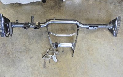
Remove both bolts on both sides at the A pillar that secure the dash to the frame.
Remove the four bolts that hold down the passenger front seat. You don’t have to remove the seat, but tip it backwards so you can remove the carpet. Now cut the soundproofing insulation around the blower motor. This will give you the room needed to get to that back screw at the blower motor.
Now just pull the dash out enough to get to the back screw at the blower motor. Disconnect the electrical connector at the motor, and remove all screws at the blower motor. Remove the blower motor from the vehicle. Remove two screws at the electrical connector side and slide out the blower motor.
Remove the two screws that hold the power unit in place and remove the power unit. Install the new power unit and blower motor back into the plastic hub.
Install the blower motor back into the vehicle, tighten all screws and connect the electrical connectors. Connect the drain tube at the bottom of the blower motor.
Now to reassemble everything… The soundproofing insulation that was removed needs to be glued back into place. Push the dashboard back into place and install the nine screws that hold it in place.
Connect the battery terminal and check to make sure the blower motor works correctly. Install the carpet and bolt down the passenger seat. Install the DIM, the top speaker, the glove compartment and the center console. Install both A pillar dash end trim pieces.
Check to make sure there are no codes in system using VIDA. Now that the job is complete, make sure again that everything works correctly.


0 Comments