
Stop chasing your tail with this methodical approach
Quiescent /kwÄ“’ esnt/ (adj.): In a state or period of inactivity or dormancy.
One of the more vexing customer concerns is a dead starter battery. Of course, sometimes this is related to a failure of the battery or charging system, but in cases where there is excessive or intermittent Quiescent (Rest) Current Draw with the vehicle switched off, proper preparation and measurement techniques can be used to identify the cause.
In cases where the excessive current draw is constant, the cause becomes significantly easier to find, since it’s always there. Regardless, the process outlined in this article will help you narrow it down efficiently. When the current draw is intermittent, that’s where we separate the men from the boys.
An intermittent Quiescent Current Draw diagnosis is arguably one of the most difficult diagnoses you will be called upon to perform, but it’s not a mystery. Years of experience from thousands of technicians have been condensed into a reliable process. Although some time is required to follow the process, following these instructions closely is your best chance for success.
The Basics
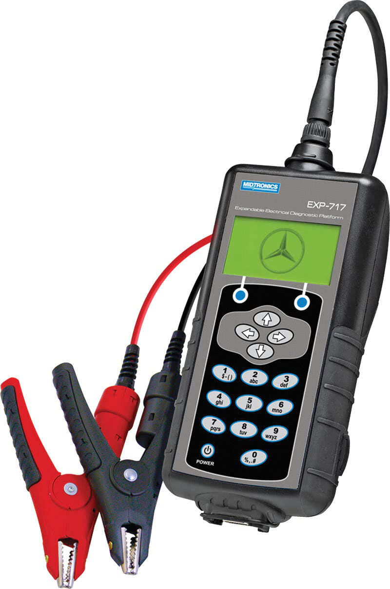
Before you start working on any intermittent dead battery concerns, the vehicle’s batteries must be checked and verified to be working properly. Use a modern conductance tester, such as the Midtronics EXP-717 that authorized Mercedes-Benz dealers use. Similar products with lower prices exist in the marketplace, but we recommend choosing a well-known brand to be sure the test results are meaningful.
In addition, the charging system must be checked for proper function. Without a robust charging system it could be that the battery isn’t being fully charged.
The customer will be one of your best sources of information here. Some excessive current draws only happen after a certain sequence of events, such as using certain vehicle functions or systems, perhaps in a specific order. Because of this fact, it is very important to hear from the customer about how they drive and what they do just before noticing the problem.
Visit bit.ly/Battery-Draw-Questionnaire to download a battery draw customer questionnaire that you can use to help ensure you have collected thorough information from the customer. Here, we’ll just summarize some of the most important questions:
- Has this happened before? When?
- Has anyone else looked at the vehicle for this problem? Details? Has anyone done any work on this vehicle in the last several months? Details?
- Where is the vehicle parked days? Nights? Locked or unlocked? How far do you drive most days? What kind of driving?
- Does the problem happen at certain times, on certain days, after certain drives, parked in a certain place? How often does it happen?
- Which vehicle features do you usually use?
- The last time this happened was when? Where was the vehicle? Was is locked? Did you unlock it with the remote? Did the key turn in the ignition? Did the instrument cluster light up? Did the car make any noises when you tried to start it?
- Describe in detail the drive before the most recent occurrence.
- Anything else you think might help us understand why this is happening?
Advise the customer that you’ll have to keep the vehicle a few days until the problem happens.
Road Test
A road test is an important part of the diagnosis. Don’t just hop in the car and drive around—instead, follow the routine described by the customer as closely as possible. Perform a road test any time you cannot duplicate the current draw. If a road test doesn’t duplicate the current draw, repeat the road test. Don’t let the vehicle sit for more than about 3 hours (except overnight)—check at least in the morning, mid-day and before leaving for the day. Document every road test, including the route taken, vehicle features used, and so on. No detail is too small to be recorded.
Resources
Although checking all of these resources thoroughly is time-consuming, it is simply impossible to perform a valid diagnosis without this step. If you don’t have access to these resources, you should get them.
- Service Bulletins: Check the Mercedes-Benz XENTRY Portal for relevant LI documents, even when the fault can be duplicated. A daily subscription is available if you are not a regular subscriber. Leverage the experience of the Mercedes-Benz technicians worldwide, as someone else may have already found your problem’s cause.
- Quick Test: Look for under-voltage codes. If there are no relevant DTCs, the customer’s concern should be re-evaluated. Patterns of DTCs could point you towards a relevant path.
- Battery Data Records: In newer models (last 10 years or so) the SAM records battery data using the Intelligent Battery Sensor (IBS). Review the recorded Driving and Engine Off cycles from the IBS using XENTRY or a compatible tester.
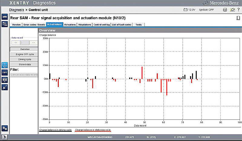
In the Battery Data Overview, a black line shows current into or out of the battery while driving, and a red line shows this while the vehicle is parked. In the overview screen example above, two significant discharges happen near data record 60 for a parked vehicle. You’ll want to look at the details of those particular data records.
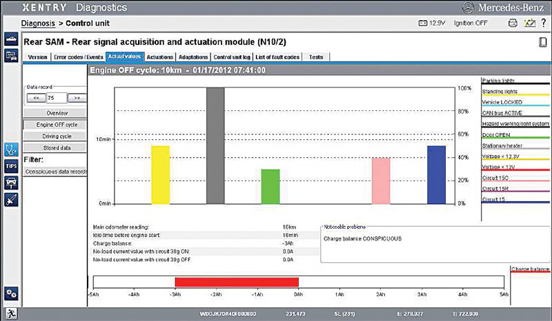
In the Engine OFF cycle screen example shown above, it can be seen that the CAN Bus (grey bar) was active for approximately 18 minutes, Circuit 15 (blue bar) was active for about 9 minutes, and a door was open (green bar) for approximately 5 minutes. We can also see that the battery lost about 3 Ah of capacity and a “noticeable problem” of Charge Balance Conspicuous is displayed.
You should also check the Driving Cycle and Stored Data screens for additional information. A few cautions when reviewing any of this data: The date/time stamps come from the instrument cluster, which is updated by COMAND. In some cases, this data can be incorrect. Note that a Driving Cycle starts when the engine is started and is only saved after the ignition is switched off, while the Engine OFF cycle data starts when the engine is switched off and is saved only after the engine is started. information is not displayed for a cycle until the cycle is complete, so if the vehicle has been sitting (Engine OFF cycle) in your shop while being tested, the data for that cycle isn’t available until after the engine has been started.
Vehicle Setup
Now that we’ve collected as much information as we could on the complaint, it’s time to set the vehicle up for long-term monitoring of the rest current. If we don’t set it up properly, we run the risk of waking up the vehicle and ruining our chances to gather accurate data. Put the vehicle in a secure place where it can sit unattended for a long period. In the shop is ideal, since outdoors weather can cause problems.
Start by gaining access to all fuse boxes, including pre-fuse boxes. Remove any covers or paneling so you have easy access.
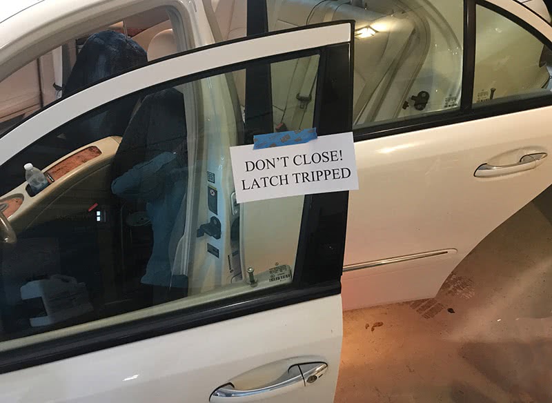
Before switching off the ignition, open all doors, hood and trunk, and close all contact switches (flip all the latches to ‘closed’). Switch off the ignition. Open, then close the Driver’s door contact switch. Then, leave the vehicle in the condition described by the customer (locked or unlocked).
Connect SD Scan if you have a XENTRY Diagnosis system. Not every current draw is caused by a CAN Bus wakeup event, but in these cases, SD Scan will help you identify the control unit responsible for the wakeup. Your task is then to identify why that control unit is waking up the Bus.
Connect a logging DVM. Many advanced digital voltmeters (DVMs) have the ability to log data over time, for example, Fluke model 289. Many other options exist, including data loggers of many types and in a wide range of prices. If is it simply not possible to log the data, at least setup Min/Max monitoring which can help identify systems that have had a high-current draw during your monitoring phase. Check that you can still access the min/max data after the meter has gone to sleep.
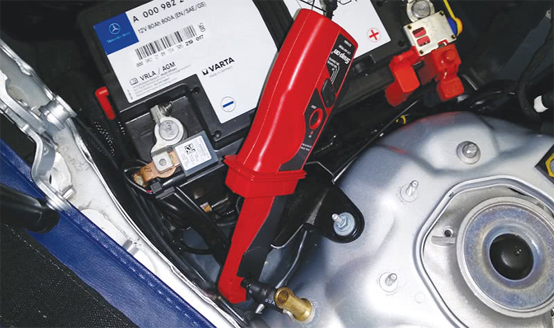
At this point, you only want to monitor the current out of the battery. We’ll get to pinpointing the problem later. Place your clamp-on current probe over the negative battery cable and connect it to your logging meter. If you don’t have a current probe, connect your meter leads between the ground and the negative battery pole. The goal of monitoring the current through the negative battery cable is to be able to see if the excessive current draw is happening or not.
Go To Sleep
No, not you, but the vehicle. Mercedes-Benz cars have had delayed switch-off of CAN Bus and other systems for at least 20 years. This means, once the vehicle is “off and parked,” you must wait a while until all the systems go to sleep. Any testing before this occurs is pointless. In most models, 60 minutes is a reasonable time to wait for this to occur.
Once the vehicle and its systems are drawing less than about 10 Amps, disconnect the negative battery cable (if you are not using an amp clamp) from the vehicle body (not from the battery!) by removing the bolt at W1 Ground and insulating the cable end. This causes all the vehicle’s current to flow through your (already-connected) meter. While in this condition, don’t do anything to cause a high current draw, or you’ll damage the meter (or at least the meter’s fuse, if there is one).
Hunt For The Problem
Now comes the fun part. After the vehicle is asleep, check the meter on the battery negative terminal. A current draw of up to perhaps 100 mA is typical and normal, although some vehicles could read a bit higher. Every time you walk past the vehicle, look at that meter: Does it show a higher current? If so, now is your chance: The problem is happening.
The strategy here is straightforward: Without disconnecting anything, measure the current draw through each fuse until you find one that’s not what it should be while the problem is happening. As you start the process, look and listen for anything obvious: noises, lights on or flickering or dim, feel the fuse boxes and modules for excessive heat.
Work your way from the battery downstream, starting with the pre-fuse box. Using an amp clamp, check the output wires (all will tend to be large) for current flow. Almost always, one wire will show more than usual, which means something downstream of that wire is your problem. (If all are OK but the problem is happening, find and measure all the unfused wires.)
Figure out which wire has the excessive current, and go to whatever fuse box or module it supplies. For example, if you found 3.1 Amps flowing on the 10 mm2 wire to the front SAM, your next destination is the front SAM.
This is worth repeating: Never pull a fuse to check current flow. This will only reset the circuit and eliminate the draw.
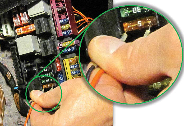
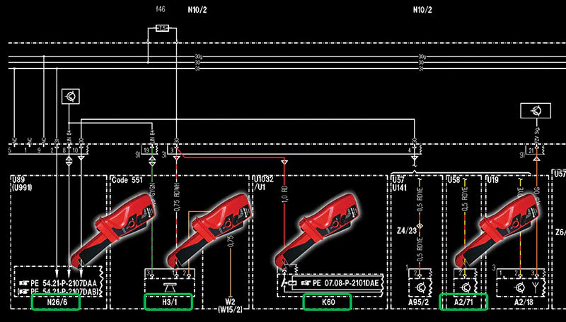
Instead, measure the voltage across the fuse, as shown in the photo above. Every fuse has accessible metal terminals at the top, and you need to measure the voltage across the fuse. Since we know the (very small) resistance of the fuse, we can use Ohm’s Law to calculate the current running through it. For example, if we have a 7.5 A fuse, the typical resistance is 0.0103 Ohms. If we were to measure 15 mV across such a fuse, we have:
| V/R=I | 0.015/0.0103 = 1.45 Amps |
A rest current draw of nearly an amp and a half is obviously way too high.
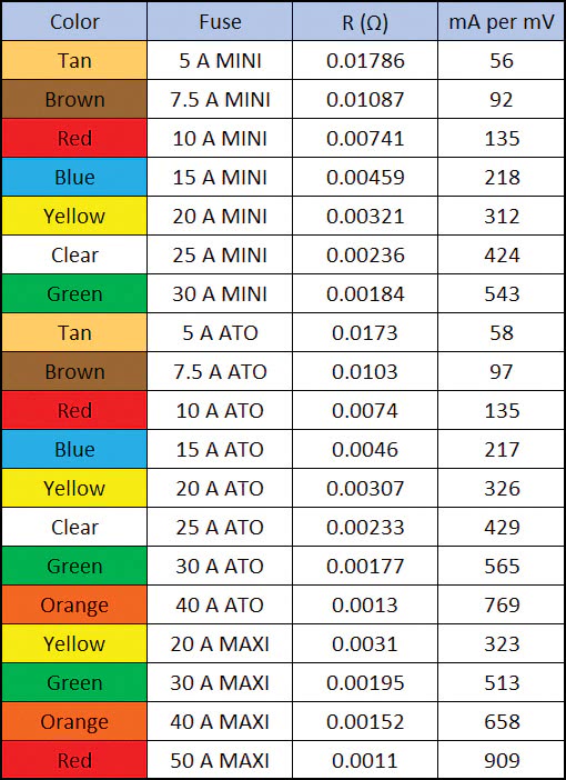
You don’t need a special “microvolt setting” meter for this, as almost any digital meter will measure with more than enough accuracy for what we need. Most fuses will read 0.00 mV and perhaps a few will read very small nonzero values. In most cases, one fuse will read significantly more, and using the wiring diagram to see what that fuse supplies will lead us to our culprit.
If you are searching for a draw that is too small for a normal DVM, please stop and regroup – you may be headed down the wrong path. Even a relatively small 150 mA on a 40 A fuse will read 0.2 mV.
Finding The Suspect
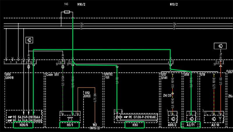
Although you may have waited several days for the fault to occur, once it does, you can work quickly to find a fuse with excessive current draw. Since most fuses supply more than one consumer, the wiring diagram in the Mercedes-Benz Workshop Information System or in Star Wiring will provide the details for that fuse. Don’t depend on the fuse chart, as it is too general. Also be sure that more of the fuse’s circuit is not shown on another wiring diagram somewhere!
Go to each consumer identified and measure the current draw using the amp clamp. If the consumers with easy access don’t show the problem, access the bottom of the fuse box and check the output wires. Remember that if a particular module is showing an excessive current draw, it may be something external to the module that is the cause. For example, a CAN Bus that doesn’t go to sleep will keep one or more control units awake, or an input switch that is hanging might give the control unit a reason to stay awake. Think outside the box here.
| IMPORTANT: Use extreme caution when removing electrical components while the circuit is energized. A short-circuit to the chassis metal can cause sparks, overheating or fire, which can injure or kill you or cause damage to the vehicle or workshop. |
Follow the wires downstream to the ultimate component causing the current draw. It is also important to attempt to identify the root cause for the faulty component. For example, if a relay has its contacts closed when they should be open, did excessive current draw from another component cause the contacts to “weld” together? Is there water from a leaky body section damaging the module?
Put some thought into it: Don’t just replace the part, find out why it failed. That way it won’t come back in a month.
The End
If you follow this process carefully every time, you will always be able to identify the cause of an excessive rest current draw. Admittedly, intermittent problems are the hardest, since you need to wait for the problem to happen. That is why it is so important to duplicate the customer’s driving and usage patterns as closely as possible. And, just as importantly, don’t bother chasing a draw when the vehicle doesn’t have one.


Very good presentation
Your article about diagnosing a quiescent current draw is very helpful, but I think it could be even more helpful for young mechanics to better understand the most common reasons the control modules don’t shut down properly. As you no doubt know, this often happens when the key is in the ignition or the Smart Key is within range. DAS is awake when something like jump starting or any other electrical item is unplugged. It causes a voltage spike that damages a control module. Even though the module often still operates, it won’t go to sleep. From my experience, the L/F seat control module is the most common fault. The L/F door is often open when someone jump starts a dead battery. If any other door or trunk lid is open, those control modules or SAM’s can also take the hit. Since the Owner’s Manual doesn’t adequately warn owners of the dangers, owners think they can jump start the battery with no regard. The other item Mercedes fails to explain is the importance of something like the Bosch BAT 35 Memory Saver. A BAT 35 should always be plugged into the OBD while working on the electrical system. The BAT 35 is more than a Memory Saver. As you know it’s also a surge protector to prevent the very voltage spike that damages the control module in the first place. In my opinion, Mercedes should warn owners to never jump start a dead battery. Or design a built-in surge protector to protect the electrical system. Every mechanic should have something like the Bosch BAT 35 and immediately plug it into the OBD as soon as they pull into their work bay. Is it really fair to consumers for Mercedes to downplay the complexity of the CAN bus? You know owners don’t understand these systems. Is it really fair to charge owners for these complicated diagnostic procedures when customers are not clearly warned of the potential damage?