There are two situations we dislike extremely when it comes to diagnosing a vehicle. Number one, when a shade-tree mechanic has attempted to repair the problem with a test light, jumper wires, and by adjusting the throttle plate. Number two is when the car comes in from a body shop. Now, most body shops are reputable places where collision repairs are done correctly and the vehicle may be passed on to someone like you to handle any mechanical and electrical problems. But its being a body shop vehicle means you can’t take anything for granted. You have to test computer controls, component operation, and wiring. This is especially true if the problem is at the point of impact. Wiring harnesses can be chaffed and/or cut in half. You should check for power, ground, shorts, and voltage drop in connections to properly evaluate these circuits.
Quick Test
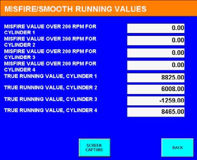
This particular Mini Convertible started, then idled poorly when it warmed up. The MIL (Malfunction Indicator Lamp) was on and it had a myriad of codes. Some of the better scan tools on the market allow you to perform what is known as a “Quick Test.†This goes through all the computer systems and looks for codes. This vehicle had a weak battery and would not complete the Quick Test with the key on and engine off even after a proper charging. This was the first hurdle we had to overcome. Now, constantly charging and jumping the battery could be the cause of many of the codes we found. The next step was to clear all the codes, run the vehicle and retest.
Most of the body control system codes stayed cleared, but MIL was still on, the engine still idled with a miss, and had a code for #3 cylinder misfire and a 1498 manufacturer code. It wasn’t a steady misfire, but it had a rhythm to it, so we thought it might be due to a specific cylinder. “Floating†misses that jump from cylinder to cylinder tend to be caused by overall incorrect mixture, something that a bad MAF or low fuel pressure can cause. This 1.6L normally-aspirated motor doesn’t have a MAF sensor. Instead, it uses a MAP sensor mounted in the intake manifold. On supercharged engines, by the way, the PCM uses two pressure sensors, one in the intake manifold and the other in the air-intake tube between the supercharger and the throttle plate.
Misfire or fuel trim first?
The next step was critical. Typically, we are taught that if the engine has a misfire and a fuel trim code, fix the misfire first. The oxygen sensor signal resulting from a misfire can cause fuel trim codes, particularly if it is intermittent. We decided to attack the misfiring cylinder first and deal with the fuel trim code later. There are several causes of cylinder misfire ranging from basic engine integrity to spark and fuel problems. Testing is definitely in order, yet we can’t waste a lot of time that we won’t get paid for. What tests could we perform in one hour to lead us to the cause of the problem?
With an OBD II generic scan tool, you would have some extra work isolating the cylinders. This vehicle has an electronic throttle, so if you shorted out a coil wire to do a crude power balance test, the PCM would quickly compensate and make it difficult to determine which cylinder is at fault. If that is all you have, then use it, but there are many aftermarket scan tools that provide Mini-specific data. You should be able to look at cylinder contribution through the scan data. Misfire detection has improved tremendously since the inception of OBD II. In this particular case, #3 cylinder seemed to be causing the rough running and needed to be investigated further.
Squeeze check
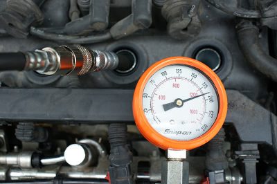
We all have are own ways of going about things. Since there are many possible causes of cylinder misfire, you can start the testing whereever you like. Here, we started with the basics — since this vehicle sat for so long anything could have been the problem. It was entirely possible that one of #3 cylinder’s valves was stuck open and either collapsed the lifter or pitted the valve seat. So, we checked compression first. Our results were 177, 200, 186 and 181 psi, cylinders 1 through 4 respectively. Certainly no cause for alarm, but we chose to oil the cylinders anyway since the vehicle hadn’t been driven in about a year. By the way, a compression test needs to be performed with the throttle held wide open and the same number of compression strokes for each cylinder.
If one cylinder takes 10 pulses to get up to 180 and another takes only five, you can’t say they’re performing the same. Try to crank the engine only five revolutions per cylinder to keep everything equal. You may have to perform a wet compression test if the readings vary more than 10%. If you don’t suspect the rings, the next step is a leak-down test to verify the valves are seating. If the engine has hydraulic lifters and hasn’t been run for a while, you may have to hold the engine at 2,000 to 3,000 rpm for five to seven minutes to allow the pressurized oil to pump up the lifters, and then perform your tests.
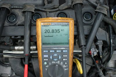
Since the engine passed the compression test, it was time to move on. We checked every cylinder with an HEI spark tester and they all fired properly. We decided to check the secondary resistance anyway so as not to overlook anything. This can quickly be accomplished by checking resistance between the #1 and #4 coil wires and the #2 and #3 coil wires. Between the former pair we got 22k ohms. The latter pair read 20k ohms. The wires for #1 and #4 are slightly longer, which would account for the increased resistance. We swapped the coil wires around, but the misfire remained in cylinder #3. So, we din’t think we had a bad plug wire or coil. Feel free to use an ignition scope if you have the equipment.
Lean miss?
With the basic engine and ignition covered, we started to think about a possible fuel issue. As luck would have it, the injectors are easy to get to. We decided to check their resistance values. All four injectors were within 10% of 14.5 ohms, so that didn’t appear to be a problem. However, just because the windings are intact does not mean the injector is not mechanically sticking. We were going to have to pull out the big guns if we were going to test the injector dynamically. There are three definitive ways to check the injector. One is to watch the “current ramp†pattern on a scope. Another is to pulse the injector a fixed amount of times and watch the fuel pressure drop.
The third way is a little more involved. It is often referred to as a cylinder contribution test. First, you need a four- or five-gas analyzer and you have to tap into the exhaust before the catalytic converter to get an untreated sample of the exhaust gas. Next, you look at the HC (hydrocarbons) on your analyzer while the engine is running. You then kill spark to one cylinder at a time. Each time you kill a cylinder the HC will rise since the raw fuel is no longer being burned in that combustion chamber. If all injectors are contributing the same amount of fuel, HC should increase equally for each cylinder. Any cylinder with a low HC increase may have a clogged injector.
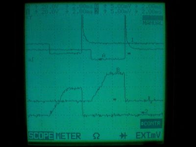
We opted to scope the injector and look at the current ramp. We were unfamiliar with a good pattern on this engine, but we had three non-problem injectors to get readings from. While the engine was missing, we looked at the pattern for #3 cylinder and compared it to that of number #1. Unfortunately, the voltage spike and current ramp patterns were identical. Typically, a low voltage spike means a weak injector return spring. The current ramp is controlled by the computer and “clipped†to about one full amp. If the injector were sticking open or closed, we should have seen a change in the way the current “ramped†upward. We could also have swapped injectors to see if the problem moved, but that would have required more time.
When it comes to diagnosing cars, time is money. We only asked for one hour to troubleshoot the vehicle once the initial codes were cleared. Any more than that and we were going to have to ask the customer for more diagnostic time, and we all know how they love to hear that it’s going to cost more money to find out what’s wrong. If we don’t figure out what the problem, we may not be able to charge for this extra time if we want to stay on good terms with the customer. We knew the compression was good, spark was sufficient, and no injector problem was obvious — we were confident it wasn’t sticking open or closed, but what if the screen is clogged?
Having the correct equipment helps. We decided to put the MotorVac fuel system cleaner on for an hour or two to address the possible screen issue while we got some other easy-money work done. In an effort to reduce injector failures, manufacturers have put in five-micron screens to keep debris out of them. This means the screens will clog easily. The MotorVac system has proven it can do a good job of cleaning the fuel rail and de-carbonizing valves. We may have had carbon accumulation on the back of the #3 intake valve, and that’s why it was missing. It’s hard to say without any history of how it ran a year ago.
A little better
The MotorVac did work. It reduced the severity and quantity of the misfires, but the problem was not entirely gone. The misfire code did not come back, but however we still had an illuminated MIL. We were using an Autologic scan tool that gave us factory-specific codes. The code we retrieved was a 1498, NOT a P1498. The code description was an air leak after the compressor. This was, however, an R50 chassis Mini Cooper with a normally-aspirated 1.6L, not the R52 Cooper S model that has a supercharger — no compressor here. We went to the Mini technical information website, www.minitechinfo.com, to get a manufacturer-specific definition of this code.
We couldn’t find a Code 1498 in our Bentley Mini Cooper repair manual for a 2006 model, but we did find a definition for a 2005 with the same 1.6 normally-aspirated motor. “Air Intake System Leak†is the definition for Code 1498. This essentially means the MAP voltage is not matching the throttle opening. We didn’t have any throttle position codes, so we didn’t test the two TPS voltages beyond what we saw on the scan tool. The throttle seemed to be responding properly. There was a crack in the air intake boot, but that’s between the air filter housing and the throttle plate so it cannot be the source of a vacuum leak. We needed to test the MAP sensor.
MAP tip-off
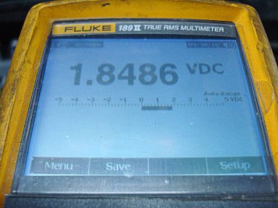
Since this motor is not supercharged, it only has one MAP sensor. We reasoned that if the MAP sensor was failing we would have a multi-cylinder misfire, not a single-cylinder one. We decided to take a quick look at the MAP sensor signal voltage anyway and rule that out. The MAP sensor reads atmospheric pressure with the key on and the engine off. With a normally-aspirated model, the MAP should read about 4.0V. At idle, we were supposed to see 1.2 to 1.3V on a vehicle with a normal 18 in. Hg of manifold vacuum. Supercharger MAP sensors have different values because they have to read pressure as well as vacuum. We were reading 1.8 volts,but why?
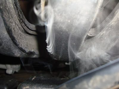
Remember, MAP voltage was high, which means manifold vacuum is slightly low. A few things can cause low manifold vacuum: a vacuum leak, late valve timing, a restricted exhaust, etc. Since we had a code for the air leak, we decided to start there. Smoking the intake manifold directly through the canister purge solenoid feed line helped us find the problem. The plastic intake manifold had cracks in it. These cracks showed up particularly on 3rd cylinder. This could definitely cause a lean misfire on only one cylinder and apparently drop manifold vacuum, increasing the MAP sensor signal voltage. Once we temporarily sealed the leaks (since this is vacuum and not pressure, you can use tape, RTV, etc. for testing purposes), MAP sensor signal voltage read 1.3 volts and the 1498 code disappeared.
As we said, one of the things we are taught is that if you have a misfire and a fuel trim code, fix the misfire first. This is typically a good place to start, but as we all have learned in this business there are no hard, steadfast rules that should never be broken. We tested all of the components related to cylinder #3. Compression, spark output, and injector function were all good. Here, the fuel trim code directed us towards the cause of the misfire. However, we did learn a few things along the way about Minis that we can use on the next one.
by Kerry Jonsson


0 Comments