In an effort to reduce wiring clutter and streamline the diagnostic process, Mercedes-Benz has advanced the application of the CAN (Controller Area Network) concept. Let’s look at the lay of the land and, more importantly, how to use CAN to find problems

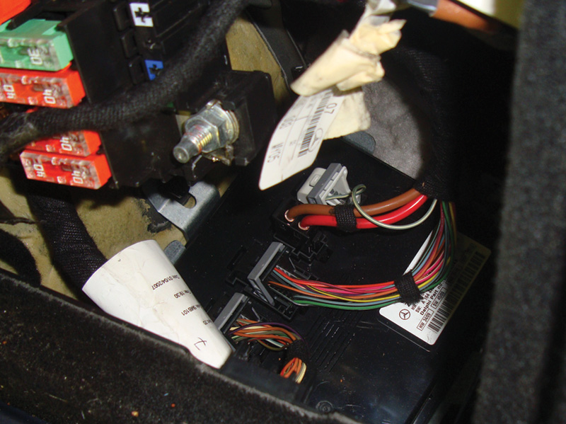
SAM modules are usually attached to or located near fuse panels. On this 164 chassis ML-Class, the rear SAM is mounted on the passenger’s side inner fender under the fuse box. It controls the hatch lock and also powers up the power seats.
Mercedes-Benz vehicles are among the most technologically advanced in the world. Nowhere is this truer than in the company’s use of Controller Area Network (CAN) systems. The goal of a CAN is to reduce complex and redundant wiring in the vehicle. This not only cuts weight and saves space, but also simplifies the diagnosis and repair process. Yes, you heard that right: It can simplify diagnostics. You do need to have the right tools and information to take advantage of what CAN has to offer. In order to diagnose and repair these systems, you should know how their components and operation. You also need a basic understanding of electricity. A light bulb needs a voltage supply and a ground, a switch changes an electrical signal from one wire to another, and solenoids and relays need to be sent a signal to complete a circuit.

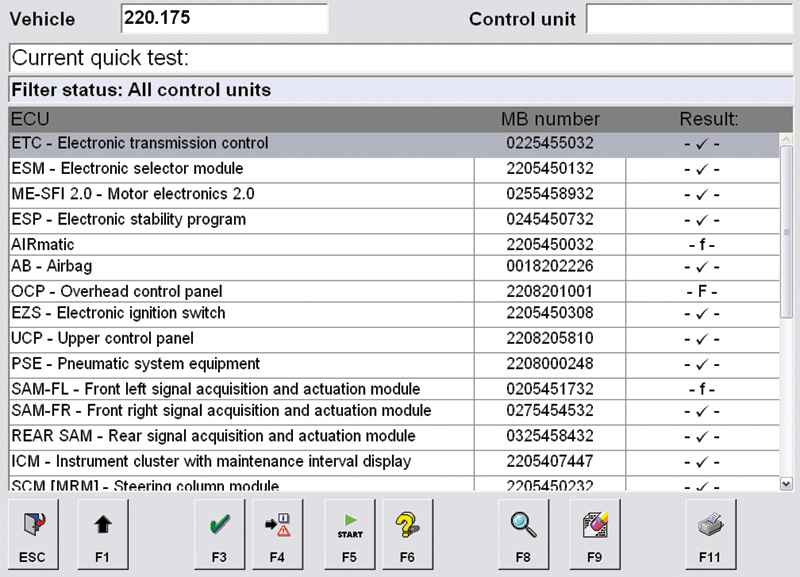
Using your SDS, you can perform a “Quick Test.†The SDS communicates with every control unit in the vehicle. Looking at the results of this test you can see there is no communication with the driver’s-side SAM. Verify that the EIS (EZS) has the SAM listed as present in the coding.
It’s where voltage supply and ground come from, and where the switch inputs go to that’s the difference. When using your remote to unlock a car there must be a control unit to receive whatever signal comes in. This control unit then has to either supply a power or ground to activate the door locks. There also have to be switches to indicate what position the locks are already in. The same goes with power windows. A switch from the master switch in the driver’s door must be run to each door to control that window, plus you need additional wiring to control the window from its own switch. With a CAN system, we can put all switch inputs to a control unit in the door and use a two-wire CAN system to communicate these inputs among control units.

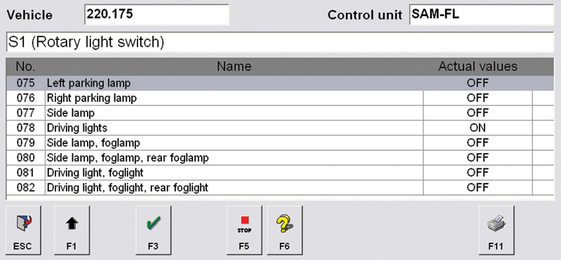
Looking at the SAM data, you can see inputs and outputs while you operate the switches. Here, we see the inputs from the light switch to the driver’s side SAM, and we can directly command outputs under the “Activations†tab.
This is what a CAN system offers. These communicating control modules have evolved from the early ‘90s with the 140 chassis S-Class. Modules that distribute power and ground and receive inputs have gone by various names in the past. They were sometimes referred to as “Combination Modules,†“All-Activity Modules,†and finally as “SAMs,†or Signal Acquisition Modules. SAMs are usually integrated with or connected to fuse/relay panels. For example, the 211 chassis has a driver’s side SAM and a rear SAM. The driver’s side SAM receives the power it distributes from the rear pre-fuse box. It both gives and receives power from the Electronic Ignition Switch (EIS) when the ignition key is turned to “Onâ€. The driver’s side SAM can then directly control some components such as the fog lights and instrument cluster. It also communicates information on the CAN-B system with other control units such as the instrument cluster and Automatic Air Conditioning (AAC).

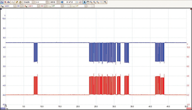
Before replacing a SAM, you should verify power, ground, and that communication lines are open. An oscilloscope will display the computer communication with a high and low square-wave signal. These signals were taken at the driver’s side SAM verifying that the problem was with the unit.
Problems found in the electrical system of a vehicle can be diagnosed one of two ways. You can go to the offending input, such as a switch, and check the operation by monitoring signal voltage. You will need to know proper switch operation. You then can go directly to the problem output and verify that a sufficient power and ground supply are present with a DMM (Digital Multi-Meter). If the switch input is working, but the output is not providing power or ground, how will you know which component has failed? With this 211 Chassis E-Class, let’s say the fog lamps are not working. The light switch input uses Bus LWR communication to send the command to turn on the fog lights. The driver’s side SAM then directly turns on the fog lights. Do we replace the light switch, SAM, or both bulbs? Of course, you should check both bulbs first, but investing in a Star Service Diagnostic System (SDS) will give you the information you need conveniently.
With an SDS, which is available for purchase from your Mercedes-Benz dealer network, you can enter the driver’s side SAM and look for Diagnostic Trouble Codes (DTCs) and monitor the data. You can watch switch inputs coming in on Bus and CAN communication lines on a software level. Depending on the control unit, you may also be able to see if the offending control unit is putting out power to the necessary circuits. With bi-directional control under “Activations,†you can command outputs and see if they work without removing panels to access the output itself or check electrical signals with a meter or scope. If you do find that the driver’s side SAM is not applying power to the circuit, you still should check powers and grounds to the SAM and verify that the wiring from the SAM to the bulbs is not damaged. If it is a communication issue, you should use an oscilloscope and verify that the CAN communication is making it to the SAM.

Once the SAM has been replaced, you will need to “Initialize†the new unit. If you can communicate with the old unit, pull the information out first, then replace the control unit and upload the configuration data. If you cannot communicate, you’ll have to enter the data manually.
If you have to replace a SAM, there are some additional steps you will need to follow to complete the repair. Whichever SAM you replace (Front, Driver’s, Passenger’s, or Rear), you will have to tailor it to the rest of the vehicle. Once again the SDS will allow you to perform “Initial Startup†of a module. You are then basically given two choices, either pull the information out of the old control unit and install the data into the new SAM, or manually enter the SAM information if you cannot communicate with the offending SAM (or module). This second option will require that you know what options are on the vehicle and how the owner had those options configured. Keep in mind that the purpose of the SAM is to control multiple functions that are close by. When replacing these SAMs, be sure to check all of the functions the SAM is in charge of.
With a paid subscription to Startekinfo.com you can look at “function charts†in the wiring diagrams. They lay out the control units that are involved in a particular function. You can then either use your SDS to look at data PIDs in each of these control units or perform electrical tests at the wiring. Either way, a more accurate diagnosis and complete repair will prevent a comeback and instill confidence in your customers that you can repair “the best engineered cars in the world.â€


0 Comments